SAMSON 430 Series 3434 Pneumatic Controller Module
Product basic positioning and adaptation attributes
Product identity: SAMSON 430 series 3434 pneumatic controller module, is a low-cost supporting module designed specifically for 3430 pneumatic controllers. The document version is the March 2007 version, and the supporting materials include information sheet T7030 EN, data sheets T7032-T7038 EN, and core data sheet T7041 EN.
Interface and Connection: The module plug can directly adapt to the self sealing connector of the 3430 pneumatic controller station, and is fixed by fastening screws for easy installation.
Pressure specification: Unified support for input and output signals ranging from 0.2 to 1 bar (3 to 15 psi), with a required gas supply pressure of 1.4 bar (20 psi), which is the basic working parameter for all models.
Core design and product model classification
Core design principle: All 3434 modules are equipped with box type comparators that work based on the principle of force balance. The proportional coefficient K ₚ can be adjusted within the range of 1-20 through a limiting valve, which is the core control parameter.
Two core models: The document focuses on introducing two models, 3434-1 and 3434-2. For other P/PI/PD/PID and special control task modules, please refer to data sheet T7040 EN. The specific model differences are as follows:
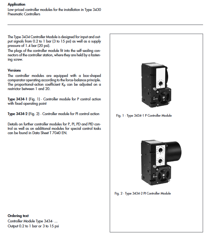
3434-1 (P control module): It only has proportional (P) control function, and its core feature is a fixed working point. The working point is calibrated at 0.6 bar (9 psi) by default.
3434-2 (PI control module): equipped with proportional integral (PI) control function, adding integral adjustment on the basis of P control, can adjust the reset time T ₙ through the flow limiting valve, and the adjustment range is 0.05~20 min.
Core working principle
(1) 3434-2 (PI control module)
The controlled variable x and the reference variable w are introduced into the membrane chambers 11 and 12 through the conversion plate A in the form of a gauge pressure of 0.2~1 bar (3~15 psi);
When x exceeds w, the force switch 21 descends and opens the plug, supplying air into the membrane chamber R2 and increasing the output pressure y;
The output pressure enters the volume of 1:1 booster 22 through T ₙ flow limiting valve 18, and its output pressure is fed back to the membrane chamber, so that the pressure in membrane chambers R1 and R2 reaches equilibrium;
The position of the force switch continues to change until the controller output pressure matches the controlled variable x and the set proportional coefficient K ₚ, and the system deviation is eliminated;
The module calibration can be completed through the zero adjustment screw, and the working direction can be selected through the conversion board A (when the controlled variable increases, the output pressure increases/decreases).
(2) 3434-1 (P control module)
The overall design and working principle are basically the same as 3434-2, with the core structural difference being the replacement of the feedback element of the T ₙ flow limiting valve in 3434-2 with a spring;
The working point is fixed at 0.6 bar (9 psi) with the help of a spring structure, without integral reset time adjustment function, only retaining the adjustment of the proportional coefficient K ₚ.
Core technical parameters and performance indicators
Except for control functions and exclusive adjustment parameters, the technical parameters and performance indicators of 3434-1 and 3434-2 are completely consistent. The core parameters are summarized in the following table:
Indicator Category Specific Parameters 3434-1 Exclusive 3434-2 Exclusive
Basic control parameter proportional coefficient K ₚ 1~20 (adjustable) 1~20 (adjustable)
Reset time T ₙ -0.05~20 min (adjustable)
Working point 0.6 bar (9 psi, fixed) No fixed working point
Pressure specification input signal 0.2~1.0 bar (3~15 psi) same as left
Output signal 0.2~1.0 bar (3~15 psi) same as left
The maximum output pressure range is 0.02~1.35 bar (0.3~19 psi), the same as the left
Supply pressure 1.4 bar (20 psi) same as left
The maximum air delivery capacity of the air path performance is greater than 1.5 m ³/h, same as the left side
Steady state air consumption<0.12 m ³/h, same as left
Accuracy index alignment deviation<1%, same as left
Tracking error<1%, same as left
Sensitivity<0.01%, same as left
Environmental impact on gas supply pressure (1.4 ± 0.1 bar)<± 0.1% same as left
Temperature effect<0.1%/℃ Same as left
Physics and environment allow ambient temperature to be -20~+60 ° C, same as left
Weight approximately 0.7 kg on the left
Core adjustment and calibration methods
Proportional coefficient K ₚ: Both modules are adjusted through flow limiting valve 14, with an adjustment range of 1-20;
Reset time T ₙ: Only 3434-2 can be adjusted through flow limiting valve 18, with an adjustment range of 0.05~20 minutes;
Zero calibration: Both modules are calibrated as a whole using zero adjustment screw 13 to ensure accuracy;
Work direction selection: By selecting through the conversion board A, it can be set to “controlled variable increase → output pressure increase” or “controlled variable increase → output pressure decrease”.