Phoenix FL MC 1000 SC (ST) Fiber Optic Converter
(1) Product Overview
Phoenix FL MC 1000 SC (ST) is a media converter designed for industrial applications. Its core value lies in achieving bidirectional conversion between Ethernet signals and fiber optic signals at a lower installation cost. With the characteristics of fiber optic transmission, it solves electromagnetic interference problems in industrial environments and extends signal transmission distance. The product complies with the IEEE 802.3 standard, is suitable for general industrial scenarios, supports standardized installation and flexible configuration, and is a cost-effective choice for industrial network expansion.
(2) Core technical parameters
Category specific parameters key information
Basic specifications and functional positioning: 10/100Base Tx → 100Mbps multimode fiber (FX standard) converter
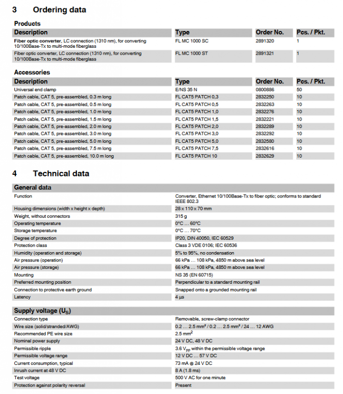
Physical dimensions: Width x Height x Depth: 28 x 110 x 70 mm
Weight 315 g (excluding connectors)
Protection level IP20 (compliant with DIN 40050, IEC 60529)
Protection category Class 3 (compliant with VDE 0106, IEC 60536)
Working environment Working temperature 0 ° C~60 ° C
Storage temperature: 0 ° C~70 ° C
Humidity range 5%~95% (non condensing)
Working pressure: 66 kPa~108 kPa (within an altitude of 4850 m)
Power supply parameters: nominal power supply voltage 24V DC/48V DC, allowable range 12V DC~57V DC
Ripple allowable value 3.6 Vpp (within the allowable voltage range)
Typical current consumption 73 mA @ 24V DC
Surge current 8 A (1.8 ms, 48V DC)
Test voltage 500V AC (continuous for 1 minute)
Special protection with anti polarity reversal protection
(3) Interface characteristics
1. RJ45 Ethernet interface
Number of interfaces: 1 (RJ45 female connector)
Transmission rate: 10/100 Mbps (adaptive or mandatory configuration)
Transmission medium: Twisted pair cable (conductor cross-section 0.14 mm ²~0.22 mm ²)
Cable impedance: 100 Ω
Maximum transmission distance: 100 meters
Core function: Supports automatic MDI/MDIX switching (without distinguishing between direct and cross cables)
Security feature: Supports FL PLUG GUARD security framework, locks RJ45 cables to prevent unauthorized changes or network access
2. Fiber optic interface
Number of interfaces: 1 (SC duplex or ST interface)
Working wavelength: 1310 nm
Transmission rate: 100 Mbps
Transmission distance (different fiber types):
F-G 62.5/125 0.7 dB/km F1000:8 km
F-G 62.5/125 2.6 dB/km F600:3.3 km
F-G 50/125 0.7 dB/km F1200:9.6 km
F-G 62.5/125 1.6 dB/km F800:5.3 km
HCS GI fiber (F-GK 200/230): 2 km
Operation warning: Do not look directly at the emitting diode or use optical auxiliary equipment to observe the optical fiber during operation, infrared light is not visible
(4) Product Model and Accessories
1. Main product models
Product Description Model Order Number Packaging Specifications (pcs/pack)
Multi mode fiber optic converter (SC interface, 1310nm) FL MC 1000 SC 2891320 1
Multi mode fiber optic converter (ST interface, 1310nm) FL MC 1000 ST 2891321 1
2. Supporting accessories
Attachment Description Model Order Number Packaging Specifications (pcs/pack)
Universal end clamp E/NS 35 N 0800886 50
CAT5 Prefabricated Jumper (0.3m) FL CAT5 PATCH 0,3 2832250 10
CAT5 Prefabricated Jumper (0.5m) FL CAT5 PATCH 0,5 2832263 10
CAT5 Prefabricated Jumper (1.0m) FL CAT5 PATCH 1,0 2832276 10
CAT5 Prefabricated Jumper (1.5m) FL CAT5 PATCH 1,5 2832221 10
CAT5 Prefabricated Jumper (2.0m) FL CAT5 PATCH 2,0 2832289 10
CAT5 Prefabricated Jumper (3.0m) FL CAT5 PATCH 3,0 2832292 10
CAT5 Prefabricated Jumper (5.0m) FL CAT5 PATCH 5,0 2832580 10
CAT5 Prefabricated Jumper (7.5m) FL CAT5 PATCH 7,5 2832616 10
CAT5 Prefabricated Jumper (10.0m) FL CAT5 PATCH 10 2832629 10
(5) Status indication and configuration function
1. LED status indicator light
Meaning of indicator light indicating status
The US (power supply) is constantly on, and the supply voltage is within the allowable range
Turn off power supply voltage too low
LNK/ACT (link/activity) is constantly on to establish an electrical link
Flashing data transmission in progress (constant flashing at high rates)
10/100 (speed, RJ45 port only), always on port working at 100 Mbps speed
Turn off the port and operate at a speed of 10 Mbps
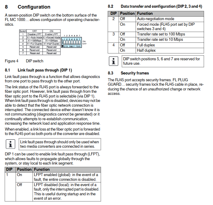
2. DIP switch configuration (7-position, located on the bottom of the product)
Switch position function configuration options
1 (LFPT) Link fault penetration open: enabled (global fault, fully connected disabled); Off: disabled (partial fault, only partially disabled interruption)
2 (Mode) Negotiation mode on: Forced mode (configured by switches 3 and 4); Off: Automatic Negotiation Mode
3 (speed) Transmission rate on: 10 Mbps; Off: 100 Mbps
4 (Duplex) Duplex mode on: Half duplex; Off: Full Duplex
5-7 reserved function not yet enabled (reserved for future use)
(6) Installation and operation specifications
1. Installation requirements
Installation carrier: NS 35 DIN rail (compliant with EN 60715 standard)
Installation position: preferably perpendicular to the standard installation guide rail
Grounding requirements: The installation of the guide rail requires a protective grounding connection through the grounding terminal block, and the module is automatically grounded (low impedance grounding) after being mounted
Auxiliary fixation: Universal end clamps can be installed on both sides of the module to prevent it from sliding on the guide rail
Installation environment: The guide rail needs to be clean, non corrosive, and avoid contact resistance
2. Installation and disassembly steps
Installation: Place the module on the guide rail from above, hook onto the upper edge of the guide rail, push forward to fit the installation surface, and confirm that it is securely fastened
Disassembly: Use a suitable tool (such as a screwdriver) to insert the latch and pull it down, gently pull the module away from the installation surface, and then lift it up from the guide rail
3. Wiring specifications
Power wiring: wire specification 0.2-2.5 mm ² (24-12 AWG), recommended PE wire specification 2.5 mm ², wiring screw torque 0.5-0.6 Nm (5-7 lb in.)
Ethernet wiring: Insert the twisted pair cable into the RJ45 interface and gently pull to confirm a secure connection
Fiber optic wiring: Remove the dust cap before connection (to prevent contamination of the transmitting/receiving components), insert the SC/ST fiber optic connector according to the correct key position, and gently pull to confirm a secure connection; Comply with the bending radius, tension, and pressure requirements of the fiber optic cable manufacturer
(7) Mechanical and certification characteristics
Vibration resistance: Complies with IEC 60068-2 standard, 10-150 Hz, 5g
Impact Test: Compliant with IEC 60068-2-24 standard (working condition), 30g, 11ms
Free fall: Complies with IEC 60068-2-32 standard, with a drop height of 100 cm
Compliance certification: Compliant with IEC 61000-6.2 standard, RoHS, WEEE 2002/96/EC certification