Pacific Scientific 6410 2-phase Bipolar Stepper Motor Driver
Product Overview
The 6410 driver is a specialized driver for two-phase hybrid stepper motors launched by Pacific Scientific, which converts pulse direction signals into winding currents to achieve high-precision and smooth operation.
Control type: Bipolar PWM chopping drive, chopping frequency 20kHz
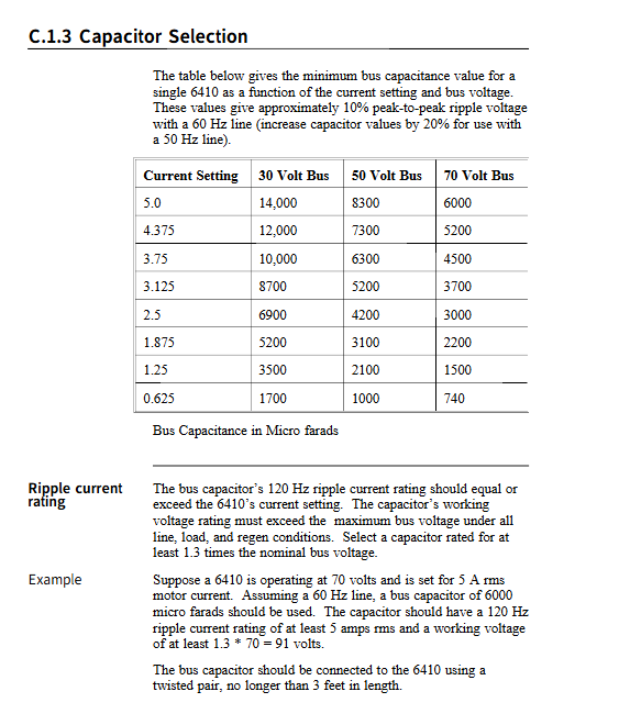
Power supply range: 24-75VDC, maximum current 5A
Current regulation: 0.625/1.25/1.875/2.5/3.125/3.75/4.375/5.0A RMS
Subdivision range: Full step -1/256 Microstep
Core advantages: Digital electronic damping eliminates medium speed resonance, optocoupler isolation, no-load current reduction, short circuit protection
Core functions and parameters
1. Microstep subdivision settings
By combining S1 switches 1-3 with J6 decimal jumper, two subdivision systems are supported:
Installation of decimal jumper, removal of decimal jumper per step (1.8 ° motor)
Step 1/2 200/400
1/2 1/4 400 / 800
1/5 1/8 1000 / 1600
1/10 1/16 2000 / 3200
1/25 1/32 5000 / 6400
1/50 1/64 10000 / 12800
1/125 1/128 25000 / 25600
1/250 1/256 50000 / 51200
2. Key control functions
Digital electronic damping: S1-4=OFF enabled, suppresses medium speed step loss and torque loss
No load current reduction (ICR): After standing still for 0.05/0.1/1 seconds, the current drops by 50%, reducing heating
Step filter: J6-1-2 is turned on to filter out * *<500ns interference pulses, up to 500kHz**
Enable polarity: J6-5-6 switching, supports high/low enable
Short circuit protection: When the motor output is short circuited, the power level is turned off and needs to be restarted to restore
3. Electrical interface
J1 (signal interface, 9-pin D-type)
STEP+/–、DIR+/–、ENABLE+/–, All-optical coupling isolation
Maximum response: 2MHz (filter off)
J2 (power interface)
DC+、DC–、 Grounding, strictly prohibit exceeding 75VDC
Wiring: Twisted pair ≤ 3 feet (0.9m)
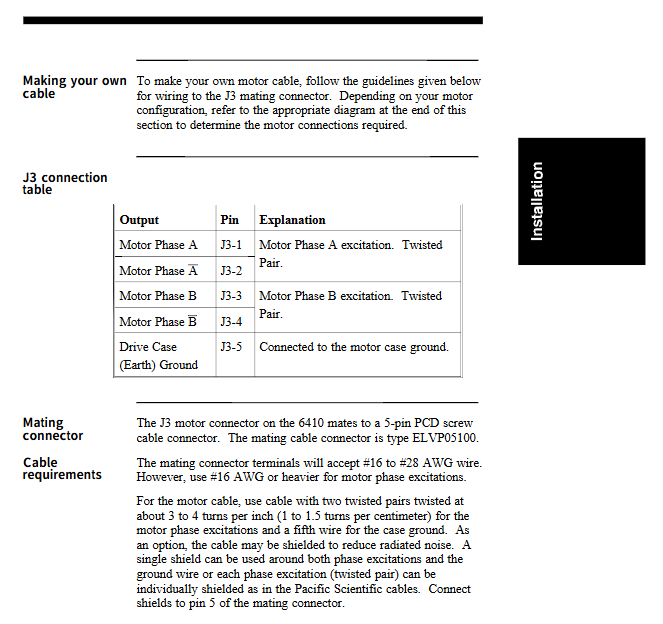
J3 (motor interface)
A+/A–、B+/B–、 Chassis Ground
Supports * * 4-wire/8-wire (series/parallel) * * motors
Installation, heat dissipation, and debugging
1. Installation requirements
Installation method: Back panel heat dissipation board installation/Side panel installation
Space requirement: Leave * * 4 inches (10cm) * * accessible space above and below
Temperature limit: Chassis temperature * * ≤ 60 ℃, environment 0-50 ℃**
2. Heat dissipation capability
Heat dissipation conditions: 25 ℃, maximum current in the environment: 45 ℃, maximum current in the environment:
Natural air cooling without heat sink 2.5A 1.25A
Equipped with cooling fins, naturally air-cooled 5A 2.5A
Adding a fan for forced air cooling significantly improves performance
3. Power on debugging steps
Power off setting S1 and J6 to factory default
Check the wiring and grounding
Power on verification to maintain torque
Send pulse test for steering and positioning
Fine tune subdivision, current, damping parameters
Protection, maintenance, and troubleshooting
1. Protection mechanism
Motor phase to phase/ground short circuit protection
Bus overvoltage/undervoltage protection
Over temperature derating and shutdown
Power on self-test and enable status output
2. Common faults and their solutions
Motor without torque: check enable, power supply, motor short circuit, current setting
Motor not turning: Confirm STEP signal, subdivision matching, and correct wiring
Opposite direction: Swap the polarity of the A-phase or B-phase winding
Medium speed out of step: activate digital electronic damping, increase power supply voltage, reduce acceleration
Certification, Quality Assurance, and Standards
Certification: UL 508C, CSA C22.2 No.142, CE (EMC/LVD)
Warranty: 2 years (for material and process defects)
Storage temperature: -55 ℃ -70 ℃
Humidity: 10% -90% without condensation