Pepperl+Fuchs K-System isolated safety barrier system
Overview and Scope of Application
Pepperl+Fuchs K-System Isolation Barrier System Manual (DOCT0187Z), aimed at system integrators, equipment manufacturers, and certified electrical personnel, provides a product lifecycle usage guide covering selection, installation, wiring, configuration, operation, maintenance, and disassembly, suitable for intrinsically safe signal isolation in hazardous 0/1/2 zones.
Core specifications of the product
1. Function definition
The K-System isolation barrier is used for the protection of intrinsically safe circuits in hazardous areas, achieving electrical isolation between the field side and the control side, while also limiting voltage, current, and energy. It supports analog/digital/frequency/HART signal conditioning.
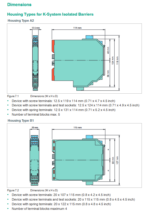
2. Shell size (3 standard widths)
Model series shell width characteristics
KC 12.5mm ultra-thin, high-density installation
KF 20mm universal type, most commonly used
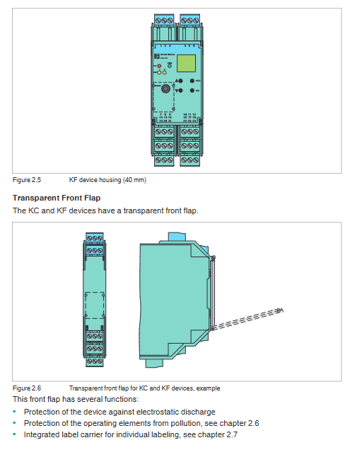
KF/KH 40mm multifunctional/high-power type
3. Characteristics of wiring terminals
Type: Pluggable terminal block
Wire diameter: maximum 2.5mm ² (14AWG)
Torque: 0.5-0.6Nm
Anti mistake: Red coded sales to prevent accidental insertion
Optional: screw terminal/spring terminal/test socket
4. Color recognition rules
Color meaning
Green DC power supply equipment
Black AC power supply equipment
Gray AC/DC wide range power supply
Blue processing danger zone signal equipment
5. Status indicator light (NAMUR NE44)
Meaning of LED color status
The green constant light power supply is normal
Internal malfunction of the red constant light device
Red flashing external circuit fault
Yellow constant light switch action
6. Configuration method
DIP switch: Basic function settings
Rotary switch: range/mode selection
Potentiometer: Zero/Range Calibration
LC display+button: parameter visualization settings
PC software (PACTware): PC side configuration diagnosis
7. Power Supply and Power Rail Bus
Power Supply Type: 24V DC/115V AC/230V AC/Wide Voltage
Power Rail UPR-03: 3-core (2 power supplies+1 fault summary)
Power Rail UPR-05: 5 cores (2 power supplies+1 fault+2 data)
A single bus supports up to 80 devices and supplies 24V DC/4A power
Installation and wiring specifications
1. Installation requirements
Rail: 35mm DIN rail (EN 60715)
Installation direction: both vertical and horizontal
High temperature applications (≤ 70 ℃): require horizontal installation and spacing
KC:≥6mm; KF(20mm):≥10mm; KF(40mm):≥15mm
Protection: Installation box IP54 or above, pollution level * * ≤ 2**
2. Wiring safety rules
Live wiring/disconnection is strictly prohibited in hazardous areas
Maintain a distance between intrinsic safety circuits and non intrinsic safety circuits
Only one wire is connected to each terminal, and multiple wires need to be crimped to the terminal
Completely disconnect the power and conduct a power test before wiring
Operation and fault diagnosis
1. Types of fault monitoring
Line fault: broken wire, short circuit
Equipment failure: internal malfunction, power failure
Fault output: normally closed contact (fault disconnected)
2. Fault summary function
Realize unified alarm for multiple devices through Power Rail, and output relay signals from the power supply module to the control system.
3. Standard signal specifications
Current: 4-20mA (NAMUR NE43)
Voltage: 0-10V/0-5V
Fault interval:<3.6mA or>21mA
Dismantling, maintenance, and repair
Disassembly: Unlock the red buckle with a screwdriver and remove the device
Maintenance: Non repairable, direct replacement as a whole in case of malfunction
Environment: -20 ℃~+60 ℃, expandable up to 70 ℃
Protection level: IP20, flame retardant level UL94 V2
Model coding rules (core position)
1 digit: K=K-System2 digits: C/F/H=Width 3 digits: D/A/U=DC/AC/Width Voltage 4 digits: 2/5/6=24V/115V/230V5 digits: Function code (CR/ST/TT/SR, etc.)
Mechanical dimensions (typical)
KC(12.5mm):12.5×119×114mm
KF(20mm):20×107×115mm
KF(40mm):40×107×115mm