
-9%

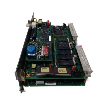
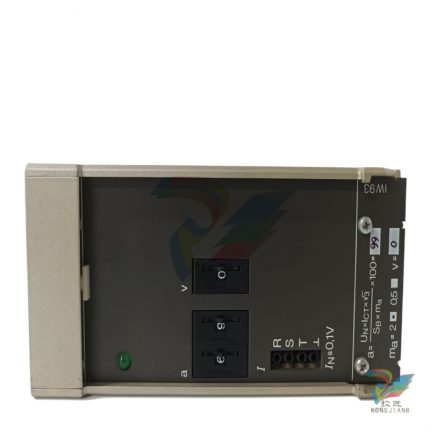
ABB T3N225 Circuit Breaker
Original price was: $27,447.00.$25,378.00Current price is: $25,378.00.个
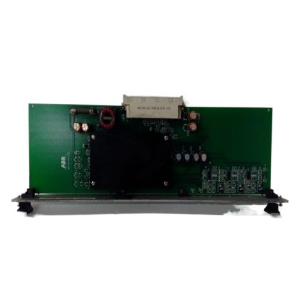
ABB SYN5302A-Z, V217 3BHB006716R0217 digital synchronizer
Original price was: $28,458.00.$26,884.00Current price is: $26,884.00.个
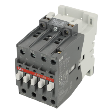
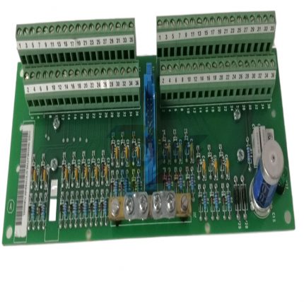
ABB A30-30-10RT three pole AC contactor
Original price was: $37,273.00.$33,737.00Current price is: $33,737.00.个
The core value of communication contactors lies in “safe and efficient control of high-power loads” – through the on/off electronic braking of electromagnetic coils, the attraction and disconnection of static contacts, remote or automatic control of the main circuit is achieved, avoiding direct contact of operators with high-voltage and high current circuits, while meeting the timing control requirements of automation systems for loads. A30-30-10RT, as a three pole contactor, is positioned as the “core of medium power load control” and is suitable for three-phase AC load control within the rated current range. The “30-30-10” model specifies the configuration of its main and auxiliary contacts, while “RT” represents the use of AC operating coils and specific installation forms.
Description
ABB A30-30-10RT three pole AC contactor
Product core positioning and application scenarios
The core value of communication contactors lies in “safe and efficient control of high-power loads” – through the on/off electronic braking of electromagnetic coils, the attraction and disconnection of static contacts, remote or automatic control of the main circuit is achieved, avoiding direct contact of operators with high-voltage and high current circuits, while meeting the timing control requirements of automation systems for loads. A30-30-10RT, as a three pole contactor, is positioned as the “core of medium power load control” and is suitable for three-phase AC load control within the rated current range. The “30-30-10” model specifies the configuration of its main and auxiliary contacts, while “RT” represents the use of AC operating coils and specific installation forms.
Typical application scenario classification:
-Motor control: As the main control switch for fans, water pumps, and conveyor belt motors, it is used in conjunction with thermal overload relays to achieve the basic control circuit of “start stop control+overload protection”, such as the start stop of ventilation fans in factory workshops and the control of water pumps in sewage treatment systems; In machine tool equipment, control the operation and stop of spindle motors and feed motors.
-Electric heating equipment control: used for power supply control of heating elements in industrial heating furnaces, electric ovens, constant temperature water tanks and other equipment. The heating time is adjusted by the on-off of contactors to achieve automatic temperature control, such as drying equipment in food processing workshops and constant temperature heating devices in laboratories.
-General distribution control: In low-voltage distribution systems, as a control switch for branch circuits, it realizes centralized power supply and power-off control for specific areas or equipment groups, such as temporary power distribution boxes at construction sites and power control for air conditioning units in shopping malls.
Core functions and technological advantages
1. Reliable electromagnetic operation and contact system
The contactor adopts a snap on electromagnetic mechanism. After the coil is energized, it generates a strong magnetic field to attract the armature, which quickly attracts the moving contact and the stationary contact. The contact resistance is small and the conductivity is excellent; After the coil is powered off, it relies on the reset spring to achieve rapid contact disconnection. The main contact is made of silver alloy material (AgCdO or AgSnO ₂), which has good wear resistance and arc resistance. It can effectively withstand the impact current at the moment of load connection and the arc erosion during disconnection, ensuring reliability under long-term frequent operation.
2. Efficient arc extinguishing capability
The built-in grid arc extinguishing chamber divides the arc into multiple short arcs when the contact is broken, rapidly reducing the arc voltage and cooling the arc to extinguish it in a very short time, avoiding arc erosion of the contact or causing phase to phase short circuits. The arc extinguishing structure is optimized for the characteristics of AC arcs, and its breaking capacity meets the IEC 60947-4-1 standard. It can safely break short-circuit currents of more than 10 times the rated current (specific values need to refer to the rated parameters), improving the safety of circuit operation.
3. Modular structure and flexible configuration
Adopting modular design, the main structure is divided into three parts: electromagnetic mechanism, contact system, and arc extinguishing chamber, which is convenient for maintenance and component replacement. Auxiliary contacts can be flexibly expanded according to control requirements. In addition to the 1 normally open auxiliary contact provided by the model, the number of contacts can also be increased by installing auxiliary contact modules to meet the signal transmission requirements of complex control circuits (such as self-locking and interlock control). Simultaneously supporting bolt fixation and DIN rail installation, suitable for different installation scenarios of distribution boxes.
4. Long lifespan and low power consumption characteristics
The optimized mechanical structure design reduces the impact force during contact attraction and disconnection, with a mechanical lifespan of over 10 million times and an electrical lifespan (under rated load) of over 1 million times, meeting the needs of frequent operation scenarios. The coil adopts efficient electromagnetic design with low operating power consumption, which not only saves electricity but also reduces coil heating, avoiding coil burnout caused by overheating and improving the overall life of the contactor.
5. Good environmental adaptability and safety protection
The shell is made of engineering plastic with a flame retardant rating of UL94 V0, which has excellent insulation performance and high temperature resistance. The protection level reaches IP20, effectively preventing fingers or foreign objects from entering the interior of the contactor. Adapting to a wide temperature working environment (usually -25 ℃~60 ℃), it can operate stably in cold and high temperature industrial workshops or outdoor distribution boxes, and has anti vibration and anti impact performance, meeting the harsh usage conditions of industrial sites.
Key technical parameters
Basic Information
Model
A30-30-10RT (Three pole AC contactor)
Main circuit parameters
Rated working voltage (Ue)
AC 400V/690V (three-phase), compliant with low voltage distribution system standards
Rated working current (Ie)
30A (under AC-3 usage category, when Ue=400V)
breaking capacity
Icu=10Ie (AC-3 category), capable of safely breaking short-circuit current
Coil parameters
Coil voltage (Uc)
Standard specifications: AC 220V, AC 380V, can be customized with special voltages
Coil power
The suction power is about 180VA, and the holding power is about 20VA (slightly different voltage specifications)
Operating frequency
Up to 360 times/hour (frequent operation), 1200 times/hour (short-term repetitive operation)
Contact configuration
Main contact
3-pole normally open (3NO), used to control the three-phase main circuit
auxiliary contact
1 pole normally open (1NO), expandable to up to 4NO+4NC (by adding modules)
Environment and Structure
working environment
Temperature: -25 ℃~60 ℃, humidity: 0~95% (no condensation)
Protection level
IP20 (enclosure), compliant with IEC 60529 standard
Installation method
DIN rail installation (35mm standard rail) or bolt fixed installation
Lifetime parameters
Mechanical lifespan/electrical lifespan
Mechanical lifespan ≥ 10 million cycles, electrical lifespan (AC-3) ≥ 1 million cycles
Installation and wiring points
1. Installation specifications
Before installation, it is necessary to confirm that the contactor model matches the load parameters (such as rated current, voltage, and load consistency). When installing with DIN rails, the contactor needs to be clamped onto a 35mm standard rail to ensure a secure installation without any looseness; When fixing bolts, the tightening torque should comply with the instructions (usually 2.5~3N · m) to avoid damaging the shell due to excessive tightening. The installation position should avoid direct sunlight, rainwater erosion, and corrosive gas erosion. It should maintain a heat dissipation distance of ≥ 10mm from surrounding heating elements (such as fuses and thermal relays), ensure good ventilation, and prevent the contactor from overheating.
2. Wiring precautions
1. Main circuit wiring: The three-phase power lines (L1, L2, L3) are respectively connected to the input terminals of the contactor main contacts (usually marked as “1L1, 3L2, 5L3”), and the load terminals (such as motors) are connected to the output terminals of the main contacts (marked as “2T1, 4T2, 6T3”). When wiring, wires that match the rated current (such as 6mm ² copper core wires recommended for 30A rated current) should be selected, and the wiring terminals should be tightened to prevent poor contact and heat generation.
2. Control circuit wiring: Connect the coil power cord to the coil terminal (usually marked as “A1, A2”), and confirm that the coil voltage is consistent with the control power before wiring to avoid coil burnout caused by incorrect voltage connection. When connecting auxiliary contacts, according to the control logic (such as self-locking control, the normally open auxiliary contacts need to be connected in parallel with the start button), connect them to the control circuit to ensure that the cross-sectional area of the wire is ≥ 1.5mm ² copper core wire.
3. Safety grounding: If the contactor housing is equipped with a grounding terminal, it must be reliably grounded (grounding resistance ≤ 4 Ω), especially in humid or dusty environments, to prevent the housing from being charged and causing safety accidents.
Common faults and troubleshooting methods
Fault phenomenon
Possible reasons
Troubleshooting method
After the coil is energized, the contactor does not engage
Inconsistent coil voltage, burnt coil, open circuit in control circuit, mechanical jamming
Use a multimeter to measure whether the control power supply voltage is consistent with the coil voltage; Measure the coil resistance (normally tens to hundreds of ohms, if it is infinite, the coil will burn out); Check if the control circuit fuse and button contacts are connected; Open the contactor and check if the armature is obstructed by foreign objects.
The noise is loud after the contactor is closed
Oil stains or rust on the surface of the armature, overly tight reset spring, and low coil voltage
Clean the contact surface between the armature and the iron core after power outage, remove oil stains and rust; Check if the reset spring is deformed and replace it if necessary; Measure the voltage at both ends of the coil to ensure that the voltage is within ± 10% of the rated value.
Contact overheating or burning out
Loose wiring, oxidation or erosion of contacts, excessive load, and failure of contact springs
Tighten the terminal block and sand the oxidized contact surface with sandpaper; Check if the load current exceeds the rated current of the contactor, and replace it with a larger contactor if necessary; If the spring elasticity of the contact is insufficient, the contact component needs to be replaced.
The load remains charged even after the contactor is disconnected
Main contact fusion welding, arc extinguishing chamber failure, auxiliary contact adhesion
Immediately cut off the main power supply and check if the main contacts are welded together due to arc welding (if welded, replace the contacts or contactors); Check if the arc extinguishing chamber is damaged and replace it if necessary; Check if the auxiliary contacts are stuck to ensure reliable disconnection.
Maintenance and upkeep suggestions
To extend the service life of the contactor, regular maintenance is required. It is recommended to determine the maintenance cycle based on the frequency of use (once every 3 months for frequent operation scenarios and once every 6 months for regular scenarios):
-Cleaning: After power failure, use a dry brush or compressed air to remove dust and debris from the surface and interior of the contactor to avoid dust accumulation and insulation performance degradation.
-Contact inspection: Check whether there are burn or oxidation marks on the surfaces of the main and auxiliary contacts. If the burn is severe (contact thickness wear exceeds 1/3), the contact components should be replaced in a timely manner.
-Coil inspection: Measure the resistance value of the coil and compare it with the standard value in the manual. If the deviation is too large (such as a significant increase or infinity in resistance value), the coil needs to be replaced.
-Mechanical component inspection: Check whether the action of the armature, reset spring, and contact spring is flexible, whether there is any jamming or deformation, and ensure that the contactor is smoothly engaged and disconnected.
Additional information
| Weight | 11.47 lbs |
|---|---|
| Dimensions | 4773 × 375 × 244 in |
Reviews (0)
Shipping and Delivery


Reviews
There are no reviews yet.