YOKOGAWA FIO I/O module with built-in safety barrier
Product Overview
Product Name: FIO I/O Module with Built in Safety Barrier
Applicable environment: Installed in Zone 2 or Division 2 areas, it can connect to on-site devices located in Zone 0, 1, or Division 1 areas
Compliance standards: Compliant with ISA S71.04 class G3, meeting ATEX and FM certification requirements (subject to corresponding certificate “special conditions”)
Environmental adaptability: working/storage temperature * * -20~70 ℃**
Isolation characteristics: The on-site interface and system have galvanic isolation, while there is no isolation between channels
Key note: When multiple channels are short circuited, all channels of the module will lose their intrinsic safety function
Module type and core technical specifications
Module type, model, core parameters, key specifications
Analog input module (isolated) ASI133 channels: 8 channels
Input signal: 4-20mA
Accuracy: ± 16 µ A
Input resistance (Power ON): 2-wire system 400-750 Ω, 4-wire system 485-925 Ω
Data update cycle: 10ms
Transmitter power supply: 16V DC or above (current limit 20mA), withstand voltage 1500V AC, maximum power consumption 5V 150mA/24V 450mA, weight ≈ 0.30kg, supports HART communication (- H model)
Analog output module (isolated) ASI533 channels: 8 channels
Output signal: 4-20mA
Accuracy: ± 48 µ A
Load resistance: 0-750 Ω at 20mA, 0-600 Ω at 23mA
Data update cycle: 10ms withstand voltage 1500V AC, maximum power consumption 5V 150mA/24V 350mA, weight ≈ 0.30kg, supports HART communication (- H model)
TC/mV input module (isolated) AST143 channels: 16 channels
Input signal: TC (8 types including B/E/J/K) mV(-100~150mV/-50~75mV)
Accuracy: TC ± 40 µ V, mV ± 80 µ V
Reference compensation accuracy: ± 1 ℃ (15-45 ℃) withstand voltage 1500V AC, maximum power consumption 5V 150mA/24V 80mA, weight ≈ 0.30kg, supports channel independent signal setting
RTD/BOT input module (isolated) ASR133 channels: 8 channels
Input signal: RTD (Pt/Ni series 2/3/4 wires), POT (3-wire 0-10k Ω)
Accuracy: Pt100 ± 150m Ω, POT ± 2 Ω
Measurement current: 150 µ A, withstand voltage 1500V AC, maximum power consumption 5V 150mA/24V 60mA, weight ≈ 0.30kg, supports channel independent type selection
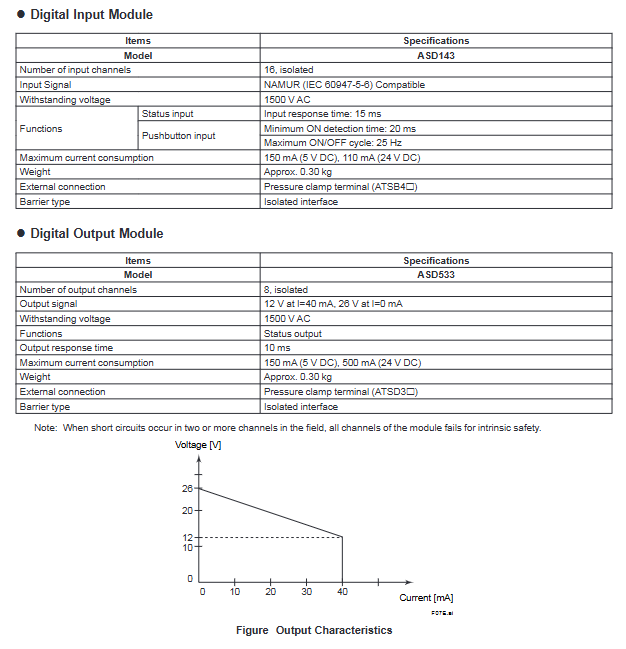
Digital input module (isolated) ASD143 channel count: 16 channels
Input signal: NAMUR (IEC 60947-5-6) compatible
Response time: Status input 15ms, button input minimum ON detection 20ms, withstand voltage 1500V AC, maximum power consumption 5V 150mA/24V 110mA, weight ≈ 0.30kg
Digital output module (isolated) ASD533 channel count: 8 channels
Output signal: 12V (40mA), 26V (0mA)
Response time: 10ms withstand voltage 1500V AC, maximum power consumption 5V 150mA/24V 500mA, weight ≈ 0.30kg
Intrinsic safety parameters (ATEX/FM)
(1) ATEX core parameters (some key modules)
Module model configuration method Uo (V) Io (mA) Po (mW) Co (nF) Lo (mH)
ASI133-S00/H00 single configuration (2-wire) 27.8 84 584 2 18
ASI133-S00/H00 redundant configuration (2-wire) 27.8 93 647 1.2 14
ASI533-S00/H00 single configuration 27.8 86 598 1.8 17
AST143-S00 single configuration (1 channel) 16.8 7 30 240 725
ASD143-P00 single configuration 9.8 21 52 1100 107
(2) FM core parameters (general characteristics)
Universal voltage Voc: 27.8V (analog class), 16.8V (TC/mV class), 9.8V (digital input class)
Short circuit current Isc: 21-108.6mA (varies by module)
Allowable capacitance Ca: 2-1100nF, allowable inductance La: 0.42-1930mH
Installation and compatibility requirements
(1) Hardware compatibility
Compatible FCU (Field Control Unit): AFV30D-S41 11, AFV30S-S31-11, AFV30S-341 11
Compatible with ESB bus node units: ANB10D-4 1/3, ANB10S-3 1/3, ANB11D-2 3, etc. (a total of 12 models)
Power module requirements: Must be paired with PW481-11, PW482-11, or PW484-11 power modules
(2) Software and Engineering Requirements
Software requirement: VP6F1700 control function running on FCS (applicable to AFV30 , Vnet/IP, and FIO)
Engineering requirement: Support VP6E5100 standard builder function
(3) External connections and dimensions
Connection method: pressure clamping terminal (such as ATSA3 □, ATSS3 , etc., supporting redundant terminals)
Module size (unit: mm): Most modules such as ASI133/ASI533 are 130 (length) x 94 (width) x 32.8 (height), with a tolerance of ± 0.8mm (≤ 120mm size)
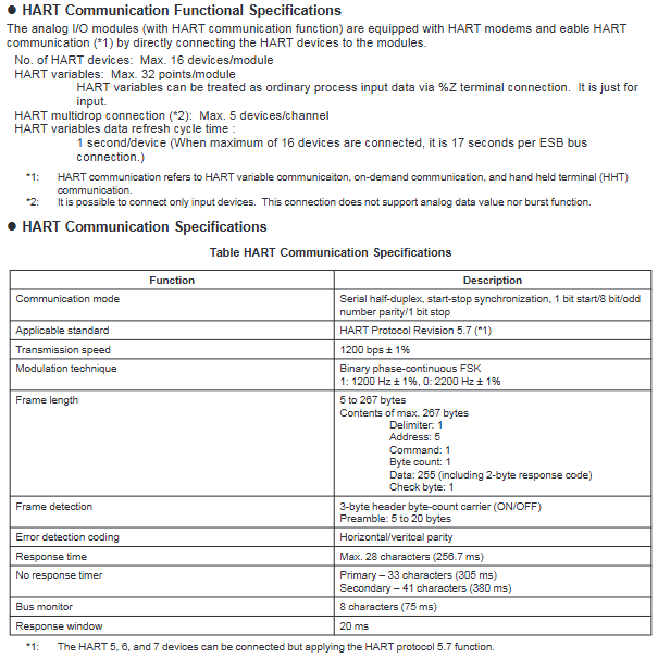
HART communication function (ASI133-H/ASI533-H models only)
(1) Core Features
Communication method: Communicate with transmitter/valve positioner, synchronously transmit 4-20mA analog signal and HART variable
Variable reading: Read HART variables through HART Command # 3, which can be used as input data for ordinary processes (% Z terminal)
Connection capability: up to 16 devices/modules, up to 5 devices per channel (multi station connection, only supports input devices)
(2) Communication specifications
Mode: Serial half duplex, start stop synchronization (1-bit start/8-bit data/odd parity/1-bit stop)
Standard: HART Protocol Revision 5.7 (compatible with 5/6/7 version devices)
Baud rate: 1200bps ± 1%, modulation method: binary phase continuous FSK (1=1200Hz, 0=2200Hz)
Data refresh cycle: 1 second per device (17 seconds per ESB bus connection for 16 devices)
Redundant configuration: Install 2 modules in adjacent slots (odd even slots), supporting dual redundant configuration
Model code and ordering
(1) Encoding rules (universal structure)
Encoding type meaning optional values
Main model module type identification ASI133 (analog input), ASI533 (analog output), AST143 (TC/mV input), etc
Suffix code 1 Function type – S (standard type), – H (with HART communication)
The suffix code 2/3 has a fixed code of 0
Option code terminal types/SA3S0 (analog input standard terminal),/SA3D0 (analog input redundant terminal), etc. (distinguished by module type)
(2) Ordering requirements
It is necessary to clearly specify the main model+suffix code+option code, for example: Analog input module with HART communication and standard terminals: ASI133-H00/SA3S0