YASKAWA MEMOCON-SC 2000 series reversible counter module
Core positioning
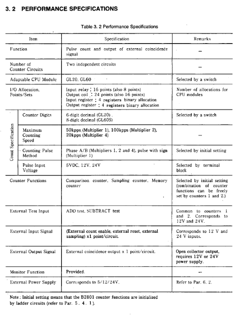
Applicable product: Reversible counter module B2801 (model JAMSC-B2801)
Core application: Pulse counting, signal comparison, data sampling and storage in industrial scenarios, outputting external coincidence signals
Compatible devices: MEMOCON-SC series CPU modules (GL20, GL60S)
Core specification parameters
Specific description of category key parameters
Environmental specifications Operating temperature 0-55 ℃ (Storage temperature -20-85 ℃)
Humidity 10-90% RH (non condensing)
Anti vibration/anti impact in accordance with JIS C0911/C0912 standards
Performance specification count bit GL20: 6 bits (0-999999); GL60S: 8-bit (0-99999999)
Counting speed X1 mode 50kpps, X2 mode 100kpps, X4 mode 200kpps
Two independent counter circuits with two counter channels
Input voltage supports 5V, 12V, 24V pulse input
Output capability: open collector output, maximum load 29V/250mA
Physical dimensions (mm) 38 (width) × 250 (height) × 104 (depth)
Weight approximately 0.6kg
Power consumption 5VDC ± 3%, 0.25A
Four major counter functions
(1) Compare counters
Core function: Pulse counting (supports carry/borrow), outputs coincidence signals by comparing the current value with the preset value
Coincidence mode: 3 types (current value>preset value, current value=preset value, current value<preset value)
Key features: After power on/reset, the current value is reset to zero from the preset value, and the coincidence signal can be reset when the output is disabled
(2) Cyclic counter
Core function: Automatically reset to zero when the current value reaches the preset value or counting width, loop counting
Default parameters: The preset value and counting width are automatically set to 100 after power on
Key feature: When the counting width is set to 0, the counter stays at 0 and does not perform addition or subtraction counting
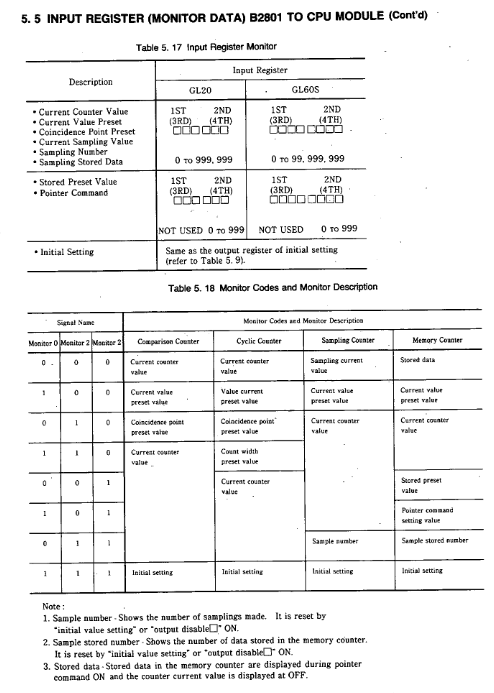
(3) Sampling counter
Core function: When receiving external sampling signals, latch the current value and store it in the input register
Sampling requirements: Sampling period ≥ 10ms, pulse width ≥ 5ms
Storage allocation: Counter 1 data is stored in input registers 1-2, counter 2 is stored in registers 3-4
(4) Storage counter
Core function: Latch the current value when triggered by external sampling signals, store up to 999 sets of data, and support reading from specified addresses
Key feature: Output coincidence signal when storage reaches preset value, clear storage data when output is disabled
Reading method: Specify the address through pointer commands, and only read stored data when the command is ON
I/O interface configuration
(1) Output coil (CPU → B2801)
Allocation quantity: 24 points (dual counter)/16 points (single counter)
Core signals: module reset, initial settings, count enable, output disable, preset commands, etc
Effective method: Some commands (such as module reset) are OFF → ON and effective, while others (such as count enable) are ON and effective
(2) Input relay (B2801 → CPU)
Allocation quantity: 16 points (dual counter)/8 points (single counter)
Core signals: READY, ACK, carry/borrow, coincidence output, scan time error, etc
Response characteristic: The carry/borrow signal only lasts for one scanning cycle
(3) I/O register
Output registers: 4, 1-2 correspond to counter 1, 3-4 correspond to counter 2, store preset values and initial settings
Input registers: 4, storing monitoring data (current value, sampled value, stored data, etc.), supporting multi-mode monitoring
Installation and wiring specifications
(1) Installation requirements
Environmental restrictions: Prohibit direct sunlight, condensation, corrosive gases, and severe vibration environments
Installation operation: The tightening torque of the module fixing screws meets the standard, and the unused slots need to be covered with dust covers
Switch setting: SW1 is used to switch the number of counting bits (OFF=6 bits, ON=8 bits), SW2 is not used
(2) Wiring requirements
Cable selection: Shielded twisted pair cable is used for signal lines, with a length of ≤ 30m (when 50kpps)
Anti interference measures: The distance from the power line is ≥ 30cm, the shielding layer is grounded at a single point, and a filter is installed on the external power supply
Terminal wiring: Signals such as pulse input, external sampling, and counting enable should be wired according to the terminal definition to avoid misconnection
Test run and troubleshooting
(1) Test running process
Before powering on, check the correctness of switch settings, terminal wiring, and voltage levels
Power on self-test: If the RDY indicator light is on, it indicates that the module is normal (self-test for about 0.8 seconds)
Function verification: Operate the pulse generator and observe the status of PHA/PHB (pulse input) and INC/DEC (counting direction) indicator lights
(2) Common troubleshooting
Common causes and solutions for fault phenomena
Non count count enable not activated, pulse input mode error, wiring error check output coil “count enable” status, pulse mode in initial settings, terminal wiring
Counting numerical error, counting digit setting error, pulse counting mode error, external interference confirmation of SW1 switch position, initial setting parameters, wiring anti-interference measures
Coincidentally, the preset value for abnormal output is set incorrectly, the output is disabled but not turned off. Check the preset value parameters and ensure that the output disabled coil is turned off
RDY light goes out, ROM/RAM error, WDT timeout module reset or power off restart, if ineffective, replace the module
Safety regulations
Operation safety: Wiring and maintenance must be powered off, touching live terminals is prohibited to avoid electric shock
Personnel requirements: Installation and wiring must be carried out by professionals to avoid wiring errors that may cause fires or equipment damage
Prohibition of modification: It is not allowed to disassemble or modify modules. Modified products are not covered by warranty and may pose safety risks