
YASKAWA GA500 series AC micro frequency converter
Product basic information
1. Product positioning and specifications
Product Name: YASKAWA GA500 Series AC Micro Drives for Industrial Applications
Model identification: CIPR-GA50Cxxxxxxxx, core specifications are classified as follows:
Voltage level, input type, power range, key parameters
200V single-phase 0.1-4.0 kW Max
200V C three-phase 0.1-22kW speed control range 1:40~1:100
400V level three-phase 0.37-30 kW protection level IP20/UL open type
Core features: Supports 5 control modes, compatible with induction motors, PM motors (including IPM/SPM), and synchronous reluctance motors (SynRM), with functions such as automatic tuning, energy saving, and dynamic braking.
2. Definition of core terms
Key abbreviations: OLV (open-loop vector control), PM (permanent magnet synchronous motor), MFAI (multifunctional analog input), MFDO (multifunctional digital output), ND (normal load), HD (heavy load)
Safety Signs: DANGER (Fatal Danger), Warning (Serious Danger), CAUTION (Minor Injury), NOTICE (Equipment Damage)
Installation specifications
1. Mechanical installation requirements
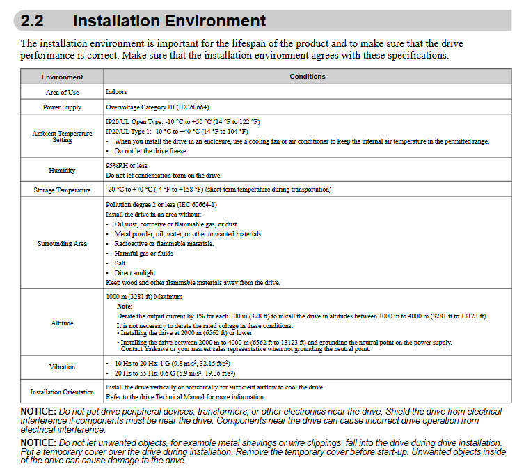
Environmental conditions: Indoor use, pollution level 2, altitude ≤ 1000m (with a 1% reduction in capacity for every 100m exceeding 1000m), vibration ≤ 1G (10-20Hz)/0.6G (20-55Hz)
Installation gap: Single driver up and down ≥ 100mm, left and right ≥ 30mm; for parallel installation, L8-35=1 should be set, and for horizontal installation, some models require an external cooling fan (such as B001-B012, which requires a 0.18m ³/min air flow fan)
Disassembly and assembly operation: The front cover/keyboard requires a specified size screwdriver (blade width ≤ 2.5mm) to avoid touching the internal capacitors (after power failure, wait for voltage ≤ 50Vdc)
2. Electrical installation specifications
Main circuit wiring:
Terminal functions: R/L1/S/L2/T/L3 (input), U/T1/V/T2/W/T3 (motor output), B1/B2 (braking resistor), grounding terminal (200V class ≤ 100 Ω, 400V class ≤ 10 Ω)
Wire specifications: Recommended 2.5mm ² for 200V single-phase B001 model, 25mm ² for 400V three-phase 4060 model, tightening torque 0.5-5.5N · m (depending on terminal size)
Control circuit wiring:
Signal mode: MFDI supports Sink/Source mode, switched through SC-SP/SC-SN jumper
Wiring requirements: Shielded twisted pair, length ≤ 50m, distance from main circuit ≥ 30cm, to avoid electromagnetic interference
Startup and Debugging Process
1. Operation preparation
Parameter settings:
General setting mode (SrUP): including 26 core parameters such as control mode (A1-02), acceleration and deceleration time (C1-01/C1-02), motor parameters (E2-01~E2-04), etc
Application preset (A1-06): Automatically optimize parameters for specific scenarios, requiring initialization (A1-03=2220/3330)
Keyboard operation: Supports LOCAL/EMOTE switching, RUN/STOP keys (STOP key priority can be disabled through o2-02), can backup/restore parameters (o3-01)
2. Auto Tuning
Tuning type:
Applicable scenarios for motor type tuning method parameter settings
Induction motor rotation tuning T1-01=0. The motor can disconnect from the load and requires a no-load rate of ≥ 30%
Induction motor static tuning T1-01=1 motor cannot rotate, load ≤ 30%
PM motor rotation tuning T2-01=4 needs to disconnect the load and automatically detect motor parameters
PM motor static tuning T2-01=1 motor fixed, suitable for non rotating scenarios
Prerequisite: Enter the motor nameplate parameters (rated power, voltage, current, number of poles), disable safe disable input during tuning, and avoid personnel approaching rotating parts.
3. Test Run
No load test: Start at a frequency of 6Hz, gradually increase to the rated frequency, and check the motor direction, vibration, and current (≤ rated current)
Load testing: Verify acceleration/deceleration response and torque output, fine tune parameters through C4-01 (torque compensation) and n1-02 (anti oscillation gain)
Checklist: Confirm power supply voltage, wiring correctness, protection parameters (L1-01 motor overload protection), and control signal effectiveness
Standard Compliance and Safety
1. Main compliance standards
EU CE: Complies with LVD (2014/35/EU), EMC (2014/30/EU), Machinery Directive (2006/42/EC), requires the use of built-in EMC filters (model suffix E) and proper grounding
UL in the United States and Canada: Compliant with UL 61800-5-1, branch circuit protection requires designated fuses (such as FWH-25A14F for B001), and control circuits require UL certified Class 2 power supply
China RoHS: Restricting harmful substances such as lead and mercury, providing a list of hazardous substances
2. Core safety requirements
Electrical safety: Wait for at least 5 minutes after power failure, prohibit live wiring/cover removal, grounding wire cross-section ≥ 10mm ² (copper core)
Mechanical safety: It is prohibited to grip the keyboard/front cover during lifting, the installation area should be free of flammable materials, and the emergency stop circuit should be independent of the frequency converter
Functional safety: Safe Disable input (H1/H2/HC) requires Source mode, with a wiring length of ≤ 30m
Operation and maintenance
1. Network communication
Supporting protocol: MEMOBU/Modbus (RS-485), with a maximum baud rate of 115.2kbps, supports master-slave configuration, and can communicate with PLC
Communication settings: The terminal resistor is enabled through DIP switch S2, and the last slave needs to be set to ON. The message format includes address, function code, and data segment
2. Troubleshooting
Common faults: OV (overvoltage), oL1 (motor overload), STPo (motor out of step), oC (overcurrent)
Troubleshooting process: After the fault occurs, power off for cooling, check the wiring → parameter settings → load status → motor insulation, and monitor the operating data (output frequency/current/voltage) through U1 xx
3. Maintenance and disposal
Regular inspection: daily (operation status, abnormal noise), regular (cooling fan replacement, 2-5 years according to model), storage (-20~70 ℃, moisture-proof)
Scrap requirements: Follow the WEEE directive, classify and dispose of electronic components and metal casings, and prohibit the indiscriminate disposal of oil/hazardous substance containing components
Summary of Key Parameters
Parameter Category Core Parameters Default Values Adjustment Range Usage
Control mode A1-02 0 (V/f) 0-8 Select control mode (V/f/OLV/PM, etc.)
Motor protection L1-01 according to A1-02 0-6 motor overload protection type (constant torque/variable torque)
Acceleration and deceleration time C1-01/C1-02 1.0 0.01-3600 years adjustment start/stop smoothness
Carrier frequency C6-02 1 (2kHz) 1- Upper limit balanced motor noise and heat dissipation
Braking resistor L8-01 0 (disabled) 0-1 enables ERF type braking resistor protection
