Woodward easyYgen-3000 series (Package P1) generator set controller
Overview
The Woodward easyYgen-3000 series generator controller is an advanced device designed specifically for controlling generator sets, providing comprehensive monitoring, protection, and automation functions. This manual (37223E version) provides a detailed introduction to the installation, wiring, and technical specifications of two models, easyYgen-3200 (plastic casing) and easyYgen-3100 (metal casing). The software version is 1.10xx, suitable for products with part numbers 8440-1816, 8440-1817, 8440-1818, and 8440-1831.
Safety Warning and Important Reminder
Critical safety warning
Independent overspeed protection: The prime mover must be equipped with an overspeed (over temperature or over pressure) shutdown device that is completely independent of the controller to prevent equipment damage or personnel injury caused by the failure of the governor or control system.
Unauthorized modifications are prohibited: Any unauthorized modifications beyond the prescribed mechanical, electrical, or operational limitations may result in personal injury and/or property damage, and render product warranty and certification invalid.
Electrostatic protection: The electronic control unit contains electrostatic sensitive components, and before operation, body static electricity must be released by contacting the grounding surface to avoid contact with components and conductors on the printed circuit board.
Important Definition
Warning: Indicates a potentially dangerous situation that, if not avoided, may result in death or serious injury.
Attention: Indicates a potential hazardous situation, which may result in equipment damage if not avoided.
Explanation: Provide other useful information that does not belong to the warning or caution category.
Installation and mechanical characteristics
Shell type
Plastic casing (easyYgen-3200)
Used for front panel flat installation with graphic LCD display screen
Protection level: IP54 when installed with fixtures, can be raised to IP66 when installed with screw kits
Overall dimensions: 282 × 217 × 99 mm
Panel opening size: 249 (+1.1) × 183 (+1.0) mm
Metal casing (easyYgen-3100)
Used for installing switch cabinet backboards without display screens
Protection level: IP20
Size: 249.6 × 227.4 × 84.1 mm
Installation key points
Plastic shell installation: can be installed using fixtures or screw kits, using all 12 screws can achieve IP66 protection level
Metal shell installation: Installed on the back panel of the switchgear using 4 screws with a maximum diameter of 6mm
Panel thickness limit: If the panel thickness exceeds 2.5mm, screws with a length equal to the panel thickness plus 4mm must be used
Detailed explanation of electrical connections
Power supply
Voltage range: 8-40 VDC
Protective grounding: A protective grounding wire with a cross-sectional area of ≥ 2.5mm ² must be connected
Recommended protective device:
Fuse: NEOZE D01 6A or equivalent product
Miniature circuit breaker: 6A/C type (such as ABB S271C6)
Voltage measurement (FlexRange technology)
Input type: Two sets of input terminals, 100V and 400V, are provided and cannot be used simultaneously
Configuration rules:
Secondary rated voltage 50-130V: using 100V input terminal
Secondary rated voltage 131-480V: using 400V input terminal
Wiring method: Supports multiple configurations including 3-phase 4-wire, 3-phase 3-wire, 1-phase 3-wire, and 1-phase 2-wire (phase neutral or phase phase)
current measurement
Variable ratio selection: supported /1A and /5A two variable ratios
Accuracy level: Level 1
Safety precautions: Before disconnecting the equipment, the secondary side of the current transformer must be short circuited
Grounding requirement: One end of the secondary side of the current transformer should be grounded near the CT
Power measurement and power factor
Power direction indication:
Actual power of generator: positive values indicate power generation, negative values indicate reverse power
Power factor: Positive values indicate inductive/lagging, negative values indicate capacitive/leading
Definition of power factor: the ratio of actual power to apparent power, with a pure resistance circuit of 1.00, inductive load as lagging power factor, and capacitive load as leading power factor
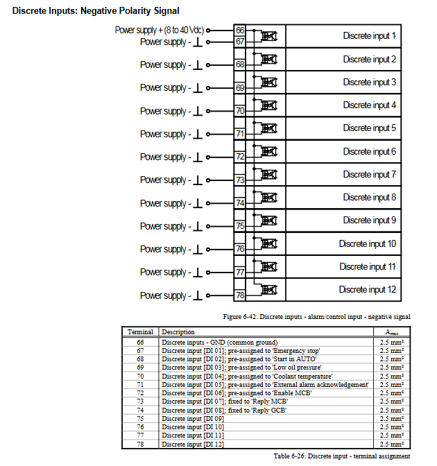
Digital input/output
Digital input: 12 channels, electrically isolated, configurable as positive or negative polarity signal
Important Warning: DI01 “Emergency Stop” is only a signal input, and the emergency stop function must be independently implemented outside the controller
Relay output: 12 channels, programmable (via LogicsManager function)
Contact type: normally open (NO) and switchable contacts
Load capacity: Universal type 2A@250VAC , 2A@24VDC
Analog input (FlexIn technology)
Sensor type: Supports 0/4-20mA, 0-500 Ω resistors, and VDO sensors
Wiring method:
Dual line sensor: accuracy ≤ 1% (resistance) or ≤ 1.2% (current)
Single line sensor: accuracy ≤ 2.5% (ensure that the voltage difference between the chassis grounding and PE is ≤ ± 2.5V)
Recommended sensors: VDO series
interface configuration
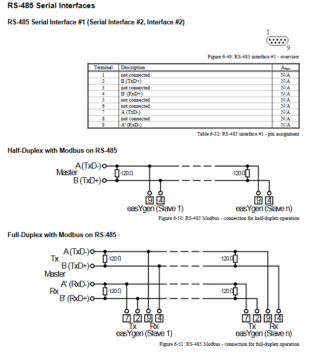
RS-485 interface: supports half duplex and full duplex Modbus communication
RS-232 interface: standard serial interface, electrically isolated
CAN bus interface: Two independent CAN channels (FlexCAN technology)
Recommended cable: shielded twisted pair (such as Lappkabel Unitronic LiyCY)
Terminal resistor: Both ends need to be connected to a 120 Ω terminal resistor
Maximum length: related to baud rate (25m at 1Mbps, 2500m at 20kbps)
Overview of Technical Data
measure performance
Voltage measurement:
100V input: rated 69/120VAC, maximum 86/150VAC
400V input: rated 277/480VAC, maximum 346/600VAC
Accuracy: Level 1, linear range 1.25 x rated value
Current measurement:
Accuracy: Level 1
Linear range: 3 times rated value on the generator side, approximately 1.5 times rated value on the grid/ground side
Analog input: 11 bit resolution, supporting 0-20mA and 0-500 Ω inputs
environmental adaptability
Working temperature: -20 ° C to 70 ° C
Storage temperature: -30 ° C to 80 ° C
Humidity: 60 ° C, 95% relative humidity, tested for 5 days
Vibration: Complies with EN 60255-21-1/-3, MIL-STD 810F and other standards
Shock: 40G, sawtooth pulse, 11ms
Certification and Protection
Electrical safety: CE mark, UL certification (for ordinary places)
Ship certification: LR (Lloyd’s Register), ABS (American Bureau of Shipping)
Protection level: Plastic shell IP54/IP66, metal shell IP20
Electromagnetic compatibility: compliant with relevant EN standards
Precision reference conditions
To ensure measurement accuracy, it is recommended to operate under the following conditions:
Input voltage: sine rated voltage
Input current: sine rated current
Frequency: Rated frequency ± 2%
Power supply: rated voltage ± 2%
Power factor: 1.00
Environmental temperature: 23 ° C ± 2K
Preheating time: 20 minutes
Special application precautions
Ship application
Power filtering: When used in bridge and deck areas, EMI filters (such as TIMONTA FSS2-65-4/3) should be equipped for power input
Additional safety devices: Additional independent safety protection devices are required to meet classification society regulations
Certification: easyYgen has obtained type certification from Lloyd’s Register of Shipping
Electrostatic protection
Before operating the electronic control unit, it is necessary to release body static electricity by touching the grounded metal surface
Avoid wearing synthetic clothing and try to wear cotton clothing as much as possible
Keep plastic, vinyl and foam materials away from the control unit and work area