Product Overview Model and core positioning: Baldor NextMove ST is a high-performance multi axis intelligent stepper motor controller that supports MintMT motion control language (structured Basic derivative) and is suitable for industrial control scenarios such as point motion, electronic cam, gear synchronization, etc. Core Features: Motion control: 3-channel stepper drive output (maximum 2A current per channel, 200kHz frequency), 1-channel external stepper shaft logic control output (3MHz frequency). I/O interface: 24 channels of 5V TTL digital input, 16 channels of open collector digital output, 2 channels of ± 10V differential analog input (12 bit resolution), and 1 channel of 0-11V analog output (8-bit resolution). Communication interface: RS232 (default baud rate of 57600), CAN interface (supports CANopen/Baldor CAN, maximum 500Kbit/s). Power supply mode: Supports the combination of driver and logic power supply (24VDC/24VAC, maximum 8.5A) or separate power supply (driver power supply 150W, logic power supply 60W).
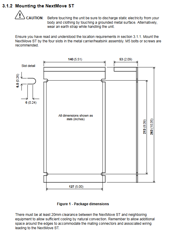
Installation process 2.1 Installation Preparation Environmental requirements: Environmental parameter specification requirements Working temperature 0-40 ℃ (32-104 ° F) Relative humidity ≤ 80% (below 31 ℃), drops to 50% at 40 ℃ (non condensing) Altitude ≤ 2000m (6560ft) The installation location is fixed indoors, away from high temperature, corrosion, and dust environments Hardware requirements: Equipment/tool specification requirements Minimum PC: Pentium 133MHz, 32MB RAM, 40MB hard drive; Recommendation: Pentium 200MHz+, 64MB RAM Cable motor wire (shielded twisted pair), communication wire (RS232/CAN dedicated shielded wire) Tool M5 bolt, screwdriver below 2.5mm, crimping tool 2.2 Key Connection Steps Mechanical installation: Vertically fixed through four slots of metal brackets, with a spacing of ≥ 20mm between adjacent devices to ensure natural heat dissipation; The device has dimensions of 263 × 140 × 53mm and weighs approximately 880g. Electrical connection: Power connection: When combining power supply, short-circuit the drive and logic power terminals. When separating power supply, connect them separately (maximum 6A for the drive power supply and maximum 8.5A for the combined power supply). Motor connection: Supports 4/6/8-wire stepper motors, 4-wire motors are connected to AB/CD phases, 6/8-wire motors need to be wired according to the corresponding pins in the manual, and any phase can be reversed if the direction is incorrect. I/O interface connection: digital input (limit/origin/emergency stop) connected to DIN terminal, digital output (drive enable/fault indication) connected to DOUT terminal; Analog input connected to AIN (± 10V), analog output connected to SOUT (0-11V); The CAN interface requires a terminal 120 Ω resistor (with JP1 jumper enabled at the end node). Communication connection: RS232 is connected to a PC through a 9-pin D-type interface, while CAN is networked through an RJ45 interface (up to 500m in length).
Operation and Configuration 3.1 Software Operation Software installation: Install WorkBench v5 (supports Windows 95/98/ME/NT/2000/XP), insert the Motion Toolkit CD to automatically start the installation wizard, default path is C: \ Program Files \ Baldor \ MintMT. Debugging process: Connect the PC to the controller (RS232 cable), start WorkBench v5, scan the serial port and select the controller to automatically update the firmware. Configure axis parameters: Set the scaling factor (e.g. 400 steps/revolution corresponds to SCALE=400), define user units (revolutions/millimeters, etc.). Motor testing: jog test (JOG. 0=2), reverse jog test (JOG. 0=-2), stop test (STOP. 0). Digital I/O configuration: DIN is allocated through software to limit/origin/emergency stop inputs, DOUT is the driver enabled output. 3.2 Core Function Configuration Scale factor setting: Convert the number of motor steps to actual units through the SCALE parameter, for example, for a 1.8 ° step angle motor (400 steps/revolution), set SCALE=400 and the user unit is “revolution”. Digital input configuration: Supports level/edge triggering and can be assigned to dedicated functions such as forward limit (LIMITFORWARDINPUT), origin (HOMEINPUT), emergency stop (STOPINPUT), etc. Parameter saving and loading: After the configuration is completed, export the parameters to the Startup block through “Upload Configuration Parameters”, save them as files, and import and load them the next time they are used.
Troubleshooting and Safety Standards 4.1 Common fault handling Troubleshooting direction The status display screen flashes error codes. Check the AXISERROR keyword and locate it using the Error Log tool (such as limit triggering, power supply abnormality) Check if the power supply wiring, motor phase wiring, JP1 jumper (output not disabled), and drive enable are activated when the motor is not running Inaccurate positioning, confirmation of correct proportional factor setting, motor load/speed/acceleration not exceeding rated value, encoder auxiliary input wiring normal Communication failure check RS232 cable wiring, PC serial port not occupied, controller power supply normal (D16 green light flashing) 4.2 Safety Regulations It must be operated by professionals and static electricity must be released before touching the equipment (touching grounded metal or wearing an anti-static wristband). The power wiring must comply with local electrical regulations, and the driver and motor must be reliably grounded to avoid short circuits. Emergency stop input cannot be used as the only safe shutdown method, and auxiliary measures such as disabling the drive and disconnecting the motor are required. Avoid installation in high temperature, corrosive, and dusty environments to prevent equipment damage.
Summary of Technical Specifications Category key parameters Power input drive power supply: 12-35VDC/12-30VAC (150W, ≤ 6A); Logic power supply: 12-35VDC/12-30VAC (60W); Consolidated power supply: 210W (≤ 8.5A) Step output maximum current of 2A per axis, output voltage of 40VDC, driving frequency of 10Hz-200kHz; Logic output frequency 10Hz-3MHz Analog I/O input: ± 10V, 12 bit resolution, 120k Ω impedance; Output: 0-11V, 30mA maximum current Digital I/O input: 24 channels of 5V TTL, 0.5mA input current; Output: 16 collector open circuits, single maximum 500mA (single channel enabled)/150mA (full channel enabled) Communication interface RS232 (maximum 115200 baud rate, maximum 3m); CAN (12-24V power supply, up to 1000m) Physical parameter size 263 × 140 × 53mm, weight 880g