Toshiba T1-16S Programmable Controller I/O Module
Toshiba T1-16S is a programmable controller that supports multi module expansion. The core supports up to 8 I/O module extensions (including 11 types such as digital, analog, thermocouple, network module, etc.). The single module I/O points cover 8-16 points, and the analog module resolution reaches 12 bits. It supports 24Vdc digital input/output, 0-5V/0-20mA/± 10V analog signal, and K/J/E thermocouple input. Network communication can be achieved through TOSLINE-F10 or DeviceNet. The I/O register adopts continuous address allocation and supports automatic/manual configuration. The module needs to be installed in a power-off state, suitable for industrial automation control scenarios.
Product Infrastructure
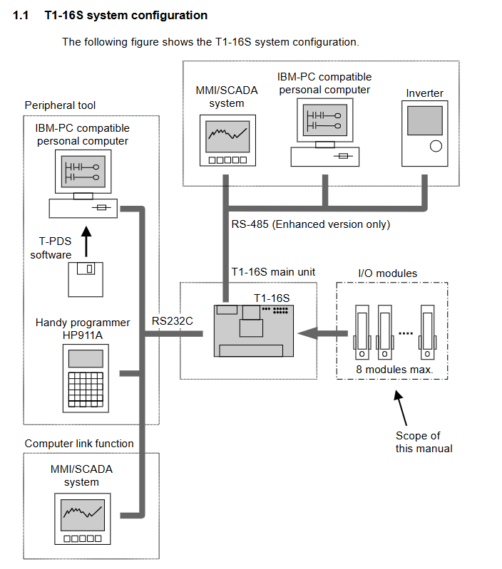
1. System composition and scalability
Core component specification details
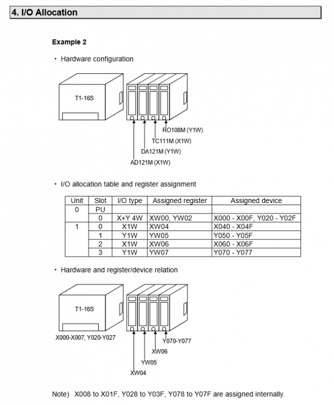
Main controller T1-16S main unit, built-in X+Y 4W I/O type (XW00, XW01, YW02, YW03 registers)
The expansion module supports up to 8 module stacks, with expansion on the right side and module connections through expansion connectors
11 types of modules (4 digital quantities, 4 analog quantities, 1 thermocouple, 2 network modules)
Maximum I/O points of 144 (fully configured with 8 16 point modules)
The main power supply unit provides 5VDC power supply, with a module power consumption of 50-400mA/module (RO108M maximum 260mA, TC111M maximum 400mA)
2. Summary of core module specifications
Module model type key parameter register allocation
DI116M 16 point DC input 24Vdc, 5mA/point, ON delay 10ms X 1W (1 input register XW)
DO116M 16 point DC output 5-24Vdc, 100mA/point, voltage drop ≤ 0.4V Y 1W (1 output register YW)
DD116M 8-in-8-out combination input 24Vdc/5mA, output 24Vdc/100mA X+Y 2W (1X+1Y register)
RO108M 8-point relay output 240Vac/24Vdc, 1A/point, mechanical life 20 million times Y 1W (1 output register YW)
AD121M 1-channel analog input 0-5V/0-20mA, 12 bit resolution, accuracy ± 0.5% FS X 1W (1 input register XW)
AD131M 1-channel analog input ± 10V, 12 bit resolution, input impedance ≥ 1M Ω X 1W (1 input register XW)
DA121M 1-channel analog output 0-20mA, 12 bit resolution, load ≤ 600 Ω Y 1W (1 output register YW)
DA131M 1-channel analog output ± 10V, 12 bit resolution, output impedance ≥ 10k Ω Y 1W (1 output register YW)
TC111M 1-channel thermocouple input K/J/E type, -200~1200 ℃, resolution 0.3-0.63 ℃ X 1W (1 input register XW)
FR112M TOSLINE-F10 remote station 750/250kbps, transmission distance 500m/1km TL-F (SW34/SW35 special registers)
DN111M DeviceNet slave station 125/250/500kbps, 4-16 word I/O data OPT (RW240-RW255, D4000-D4095)
Core functions and technical features
1. Signal processing capability
Digital module: Input supports 24Vdc (± 10/-15%), output supports 5-24Vdc, relay module supports 240Vac/24Vdc load, single channel maximum 1A.
Analog module: 12 bit resolution (1/4000), conversion cycle 2ms, accuracy ± 0.5% FS (25 ℃), ± 1% FS (0-55 ℃), input/output range covering 0-5V, 0-20mA, ± 10V.
Thermocouple module: supports K (-200~1200 ℃), J (-200~800 ℃), E (-200~600 ℃) types, input impedance ≥ 1M Ω, conversion period ≤ 20ms.
Anti interference design: The digital quantity can withstand a voltage of 1500Vac (1 minute), and the analog quantity is isolated by optocouplers. It is recommended to use shielded twisted pair wiring.
2. Communication and network functions
Core characteristics of network module communication parameters
FR112M (TOSLINE-F10) transmission speed of 750/250kbps, bus topology at a distance of 500m/1km, 1-letter receiving/1-letter sending, station address 0-30
DN111M (DeviceNet) transmission speed of 125/250/500kbps, node address 0-63 at a distance of 100m, 4-16 word I/O optional, supporting Polling mode
3. I/O configuration and register allocation
Configuration method:
Automatic configuration: By executing commands through the programmer, the main unit automatically detects hardware and generates a configuration table.
Manual configuration: Set the I/O type (X/Y/X+Y/TL-F/OPT) slot by slot, supporting 1-16 word register allocation.
Register rules:
Continuous address allocation for input register (XW) and output register (YW), with the first half of the X+Y type being XW and the second half being YW.
Special modules: FR112M occupies SW34/SW35, DN111M occupies RW240-RW255 (status/request), D4000-D4095 (I/O data).
Status display: The I/O status of each module can be switched and displayed through the main unit LED, which can be configured through the special register SW54 (0=main unit, 1-8=module slot).
Installation and safety regulations
1. Installation requirements
Module installation: It must be powered off and stacked from the right side of the main unit. Unused expansion connectors need to be covered with dust covers.
Wiring specifications: The digital module uses a 24 pin connector (optional welding type/flat cable type), the relay module uses M2 screw terminals (wire diameter 0.3-1.25mm ²), and the analog/thermocouple uses shielded twisted pair.
Environmental adaptation: The working temperature is 0-55 ℃, and the digital input capacity decreases with the ambient temperature (the number of ON points is halved at 60 ℃).
2. Safety regulations
Electrical safety: The module has a withstand voltage of 1500Vac (digital)/500Vac (analog) and an insulation resistance of ≥ 10M Ω.
Operation taboos: Do not touch electronic components on printed circuit boards, do not plug or unplug modules with power on to avoid the risk of short circuits.
CE certification: The DeviceNet module needs to be equipped with a ferrite core (within 10cm of the cable) and a shielding layer grounded (≤ 100 Ω) to meet the EMC directive.
Malfunctions and Maintenance
Fault indication: DN111M displays status through dual color LED (green=normal communication, red=fault, orange=power on self-test).
Error handling: When there is a network communication failure, FR112M triggers S00D special relay, while DN111M maintains the previous data.
Module replacement: Supports individual module replacement, and after replacement, it is necessary to ensure that the I/O configuration table is consistent with the hardware.