REXROTH VT-HNC100… 3X Series Digital Axis Controller
The REXROTH VT-HNC100… 3X series digital axis controller is a programmable NC controller suitable for 1-4 electro-hydraulic axes, supporting position, pressure, speed, differential pressure control, and axis synchronization functions. It is compatible with bus protocols such as PROFIBUS DP, CANopen, PROFINET RT, etc. The power supply voltage is 18-30VDC, the protection level is IP20, and it needs to pass WIN-PED ® 6/7 software debugging, installed on the 35mm standard top cap guide rail of the control cabinet, suitable for industrial scenarios such as machine tools, plastic machinery, presses, etc. It is prohibited to use it in explosive environments and safety related control circuits.
Product Overview
Core positioning: VT-HNC100… 3X is a programmable digital axis controller launched by Bosch Rexroth, designed for closed-loop control of 1-4 electro-hydraulic axes in industrial scenarios. It can achieve multi-dimensional control and axis synchronization functions and is the core control component of machine tools, plastic machinery and other equipment.
Product Series
|Model suffix | Number of axes | Key features | Encoder support|
|VT-HNC100-C-3X | 1 (Compact) | High integration, simplified interface | SSI|
|VT-HNC100-1-3X | 1 | Standard single axis control, rich expansion interfaces | Incremental/SSI|
|VT-HNC100-2/3/4-3X | 2/3/4 | Multi axis synchronous control, supporting group synchronization | Incremental/SSI|
Core strengths
Comprehensive functionality: covering position, pressure, speed, and differential pressure control, supporting position dependent braking and alternating control (position/pressure).
Strong compatibility: Supports multiple bus protocols such as PROFIBUS DP, CANopen, PROFINET RT, EtherNet/IP, etc.
Industrial adaptation: resistant to vibration and impact, suitable for harsh industrial environments, with a protection level of IP20.
Easy debugging: through WIN-PED ® Software implementation for parameter configuration, programming, and diagnosis.
Key technical parameters
(1) Basic parameters
Category specific indicators
Power supply specification 18~30VDC, residual ripple ≤ 1.5Vpp, operating current 1~4A (depending on model and external components)
Environmental conditions: working temperature of 0-60 ℃, storage temperature of -20~70 ℃, no conductive pollutants (acid, alkali, salt, etc.)
Mechanical dimensions vary depending on the model, compatible with 35mm top cap guide rails (TH 35-7.5/15)
Protection level IP20 (to avoid dust and liquid intrusion)
The cable requires a maximum length of 2 meters for signal cables, and copper braided shielded cables are required. The shielding layer should be grounded at one end
(2) Bus and communication parameters
Key parameters of bus type
PROFIBUS DP addresses 1-127, supports DP V0/V1 protocol, terminal resistors need to be externally connected
CANopen baud rate 10k~1000kbit/s, addresses 1~127, no built-in terminal resistor
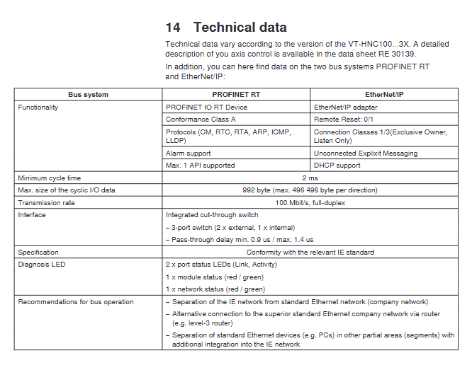
PROFINET RT has a minimum cycle of 2ms, with a maximum cyclic I/O data of 992 bytes (496 bytes in both directions) and a transmission rate of 100Mbit/s
EtherNet/IP supports Exclusive Owner/Lasten Only connection classes, supports DHCP, and has a transmission rate of 100Mbit/s
RS232 is used for PC debugging, only for point-to-point communication
Core functions and adaptation scenarios
Core control function
Basic control: open-loop/closed-loop control of position, pressure, speed, and differential pressure.
Special functions: position dependent braking, alternating control (position/pressure mode switching), multi axis synchronization (up to 4-axis group synchronization).
Process functions: process programming, cam curve, trajectory planning.
Adaptation scenario
Applicable equipment: machine tools, plastic machinery, specialized equipment, press machines, transmission systems.
Prohibited scenarios: Explosive environments, safety related control circuits defined by DIN EN ISO 13849, personnel transportation equipment.
Installation and wiring specifications
Installation requirements
Installation location: Inside the control cabinet, away from power electronic equipment such as frequency converters, to avoid strong magnetic field interference.
Wiring rules: Signal cables and power cables should be wired separately, and parallel laying is prohibited; The shielding layer of the shielded cable is only grounded at the controller end.
Power supply requirements: The power module should be placed as close as possible to the controller, and the power supply and return lines should be laid in parallel to reduce voltage drop.
Key points of wiring
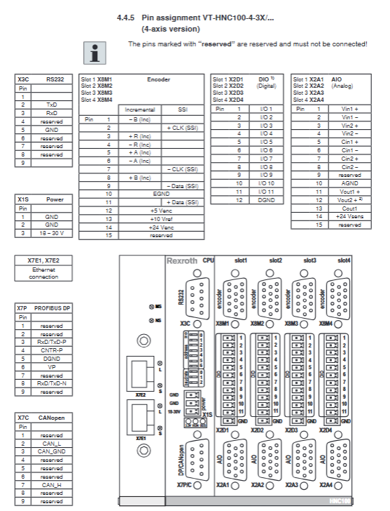
Encoder interface (X8M): Supports incremental (A/B/R signals) and SSI absolute (CLK/Data signals), with a power supply of 24V/5V.
Analog I/O (X2A): Supports 4-20mA pressure sensor signal input, analog output controls electro-hydraulic valves.
Digital I/O (X2D): Up to 20 digital outputs, 11 digital inputs per axis, used for switch control.
Bus interfaces: PROFIBUS DP (X7P), CANopen (X7C), Ethernet (X7E1/X7E2).
Debugging and operation
Debug preparation
Hardware: Controller, PC (Windows XP/7), RS232 cable (R900776897) or USB-RS232 converter (R901066684).
Software: WIN-PED ® 6 (Basic Edition) WIN-PED ® 7 (Ethernet version, supports PROFINET RT/EtherNet/IP), can be downloaded for free from the official website.
Debugging process
Physical connection: Connect the PC to the controller using RS232 or Ethernet cable, and provide power (18-30VDC) to the controller.
Software installation: Install WIN-PED ® And the firmware corresponding to the controller type.
Communication establishment: Configure communication parameters in the software (default baud rate of 9600bps, IP address needs to be manually set).
Project operation: Upload existing project data or create a new project, configure axis parameters, control modes, and bus data exchange.
Initialization: Download project data to the controller, restart to complete initialization, and the LED displays RUN (green constant) to indicate readiness.
LED status description
|LED Name | Status | Meaning|
|3.3V | Always on | Controller power supply is normal|
|RUN | Always on/flashing | Always on=initialized; Blinking=Uninitialized|
|BUS | Always on | Bus communication is normal|
|NS | Green constant light/Red constant light | Green=Network connection established; Red=IP address conflict|
|L | Always on | Ethernet link activation|
Maintenance and safety regulations
routine maintenance
Cleaning: Use only a dry and dust-free cloth to wipe the outer shell, and do not use solvents or corrosive cleaning agents.
Inspection: Check the tightness of cable connections and the sealing of plugs at least once a year, and replace damaged cables immediately.
Repair: The controller cannot be disassembled for repair. In case of malfunction, it needs to be replaced as a whole and returned to the designated service address of Bosch Rexroth.
Safety Specifications
Personnel qualifications: Only professionals with knowledge of electrical installation and control technology are allowed to operate.
Power supply safety: Only use PELV (Protection Extra Low Voltage) power supply, avoid plugging and unplugging plugs when live.
Environmental taboos: It is prohibited to use in explosive or conductive pollutant environments.
Modification taboo: It is prohibited to modify the controller without authorization, otherwise the warranty will be invalidated.