MOOG M3000 ® Control System QAIO 16/4 Analog I/O Extension Module
The M3000 jointly launched by Moog and Berghof Automation Technology ® The user manual for the QAIO 16/4 series analog I/O expansion module (QAIO 16/4-V voltage type, QAIO 16/4-A current type) of the control system is a modular automation system based on CANbus, suitable for medium to high performance industrial control scenarios. The core consists of 16 analog inputs and 4 ± 10V analog voltage outputs, paired with a * *+10V reference voltage source * *. The input resolution is 11 bit+symbol, the working temperature is 5 ° C to 50 ° C, and the protection level is IP20. Shielding measures need to be taken to ensure accuracy. The manual specifies in detail the technical parameters, wiring installation, operation and maintenance, sensor/actuator connection, and safety specifications of the module. At the same time, it is clarified that the module does not have CE labeling, and users need to ensure the electromagnetic compatibility compliance of the system by themselves. The sentence is:.
Core features and technical parameters of the product
(1) Core functions and classification features
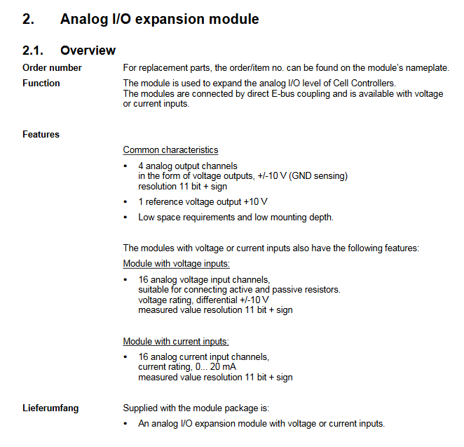
The module is used to expand the analog I/O capability of Cell Controllers, directly coupled through E-bus, and is divided into two models. The general characteristics and model specific characteristics are as follows:
General features: 4-channel ± 10V voltage output (GND detection), 1-channel+10V reference voltage output, small size/low installation depth, output resolution of 11 bits+symbol;
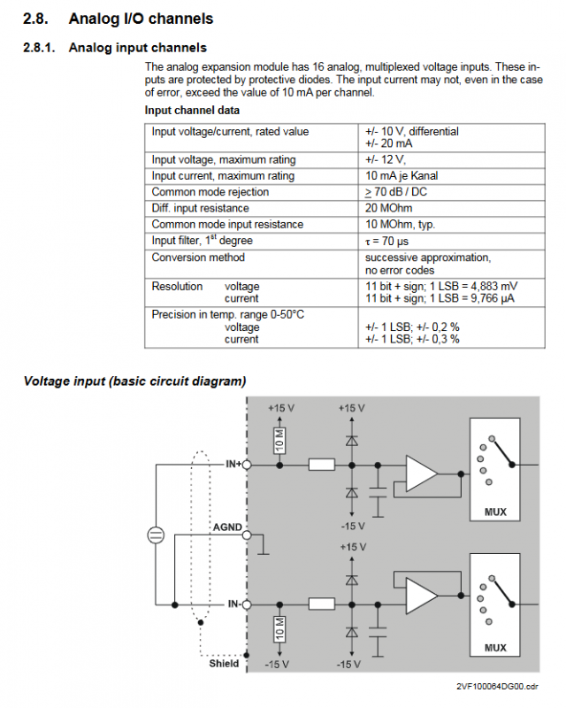
QAIO 16/4-V (voltage type): 16 differential ± 10V voltage inputs, compatible with active/passive resistors, resolution of 11 bits+symbol;
QAIO 16/4-A (current type): 16 channels of 0-20mA current input, resolution of 11 bits+symbol.
Supply list: only includes analog I/O expansion modules of corresponding models (voltage/current type).
(2) Key technical parameters
The core technical parameters of the module are all industrial grade standards. The physical, environmental, and power supply parameters are shown in the table below. The key parameters for analog input/output and reference voltage are detailed in the subsequent subdivision table
table
Category Technical Parameters
Size 124 × 170 × 85.5mm (modular size B=113/118.5mm)
Weight approximately 550g
Installation method NS 35/7,5 EN 50022 DIN rail
Working temperature 5 ° C to 50 ° C (no condensation)
Protection level IP20
Insulation test with 500VDC test voltage, in compliance with EN 61131-2
Supply voltage SELV DC+24V, maximum 0.3A, with reverse voltage protection
Maximum 300mA under no-load power consumption of DC+24V
Electrical isolation and E-bus optoelectronic isolation; Power supply and analog channels are not isolated
Four amber LED status indicators display L+, ± 15V,+5V, and OUT-ENA status respectively
EMC requires users to implement shielding measures, with emissions complying with EN 50081-2 and anti-interference complying with EN 50082-2
(3) Analog input/output/reference voltage core parameters
table
Category subdivision index Voltage type Input current type Input analog output Reference voltage source
Number of channels -16 16 4 1
Rated range – ± 10V (differential) 0~20mA ± 10V (floating)+10V
Resolution -11 bits+symbol 11 bits+symbol 11 bits+symbol-
LSB value -4.883mV 9.766 μ A 4.883mV-
Accuracy 25 ° C maximum error ± 0.1% full-scale ± 0.2% full-scale ± 0.15% full-scale 0.1%
Accuracy: Maximum error in the full temperature range ± 0.2% of full range ± 0.3% of full range ± 0.3% of full range-
Input impedance signal range 10M Ω 50 Ω —
Maximum output current -5mA 5mA
Protection Function Short Circuit Protection – Permanent Short Circuit Protection (Ikmax=25mA) Permanent Short Circuit Protection (Ikmax=25mA)
Common mode rejection DC/50/60Hz ≥ 70dB ≥ 70dB ± 2V Common mode range-
Overload capacity: Continuous maximum overload ± 30V 50mA —
Conversion speed channel transmission time<1ms<1ms<1ms<1ms-
Load requirement: capacitive load -<1000pF-
Load requirement: Resistive load – ≥ 2k Ω-
Module installation and wiring specifications
Installation requirements: The module must be installed inside a metal shielded cabinet/enclosure, and the cabinet must be isolated from interfering components and cables through measures such as wiring separation and component space isolation; The signal cable needs to be shielded at both ends, and the shielding layer of the cable at the entrance of the cabinet needs to be laid flat and grounded. Open wiring is strictly prohibited.
Wiring method: using vertical front wiring, equipped with a press type terminal block, supporting screw/crimping/clamping connections; The module is labeled with clear analog I/O channels, reference outputs, and terminal assignments for power supply, and must be wired according to the identification.
Shielding and anti-interference:
Low frequency interference (such as 50Hz power frequency) is offset by a differential measurement system and high common mode suppression;
High frequency/pulse interference needs to be isolated through shielding measures, and the cable shielding layer needs to be grounded at both ends on site (outside the cabinet);
The interaction between all analog components and auxiliary power supplies needs to be considered as a whole to ensure system immunity.
Module operation and usage
Initialization and recognition: Module recognition and initialization are automatically completed by the upstream Cell Controller operating system, without the need for dip switch settings; If the+24V power supply is interrupted or the E-bus transmission is interrupted, the analog output will reset to 0V and the OUT-ENA LED status will change.
Data measurement and conversion:
The transmission of measurement and data to CAN nodes is cyclic, controlled by the operating system API, and AD conversion does not require a startup signal;
Data conversion formula: U=10V × AD/2 ^ 15 (voltage), I=20mA × AD/2 ^ 15 (current), AD is the output value of the analog channel;
Over range output: positive over range is+32752 (+9.995V), negative over range is -32768 (-10.000V); When the sensor fails, the corresponding channel reports+9.995V to the controller.
Sensor/actuator connection: Differentiated wiring according to sensor type is required, with the following core requirements:
Floating ground sensor: Connect IN+/AGND through a 2-core shielded wire, and bridge at least one measurement input (IN -) to AGND to avoid capacitive signal coupling and false measurement;
Active sensor with auxiliary power supply: Connected to IN+/IN – through a 2-core shielded wire, sharing the same power supply with the module. The AGND module remains open to ensure potential balance;
Sensors using internal reference voltage: Connect IN+/IN -/Ref/AGND through a 3/4 core shielded wire. Potential sensors need to bridge idle inputs to AGND to avoid reference voltage overload.
Analog output usage: The output is a floating ground ± 10V voltage, and each output is equipped with AGND (analog ground) and REF (common ground) terminals, which can compensate for ground bias (must meet | UREF |<2V); The SENSE line is directly connected to the actuator ground and cannot be used alone as feedback.
Maintenance and after-sales standards
Daily maintenance: The module is maintenance free and the ventilation openings need to be kept unobstructed; Cleaning can only be done with dry, lint free cloth, and the use of cleaning agents is prohibited.
Repair requirements: Only the manufacturer or its authorized engineer can carry out repairs. Unauthorized repairs will void the warranty.
Scrap disposal: After the module reaches the end of its service life, it can be returned to the manufacturer for paid recycling, and the manufacturer will handle and recycle it uniformly.
Warranty policy: According to the statutory warranty conditions, if the module is repaired/modified without authorization, the warranty will immediately become invalid.
Nameplate information: The module nameplate includes barcode, identification number, module model, order number, version, power supply voltage, production date, etc. When ordering, only the model/order number needs to be provided. When replacing the module, the software version can be read through the CNW tool and the project version can be reloaded.