Kollmorgen SERVOSTAR ® CD series digital servo motor amplifier
Kollmorgen SERVOSTAR ® The installation and operation guide for the CD series digital servo motor amplifier (divided into Series 2/5, supporting 3/6/10A continuous current) is designed to adapt to industrial motion control scenarios. It supports three control modes: current/torque, speed, and position, and is compatible with three types of feedback devices: rotary transformers, incremental encoders, and sine encoders. It has RS-232/RS-485 serial port and SERCOS fiber communication capabilities, and is configured and monitored with MOTIONLINK software. The operating temperature ranges from 5 ° C to 45 ° C, with a protection level of IP20. The manual provides detailed product parameters, installation wiring, communication configuration, system operation, fault diagnosis, and firmware upgrades throughout the entire process. It also includes motor wiring diagrams, encoder type instructions, and other appendices to ensure safe and stable equipment operation.
Manual and Product Basic Information
Product positioning and series differentiation
Core attributes: Digital servo motor amplifier, suitable for industrial motion control scenarios such as machine tools, packaging, electronic assembly, etc
Series versions: Series 2 (model number 5 is 2, such as CR06250), Series 5 (model number 5 is 5, such as CR06550), Series 5 is an upgraded version that is compatible with the form and functions of Series 2, with new features such as DSP control and extended I/O
Model code: Cx zz 5yw (C=CD series, zz=continuous current: 03/06/10A, 5=logic power supply, y=feedback type: E=encoder/B=sine encoder/R=rotary transformer, w=control interface: 0=analog/1=SERCOS/4=DeviceNet)
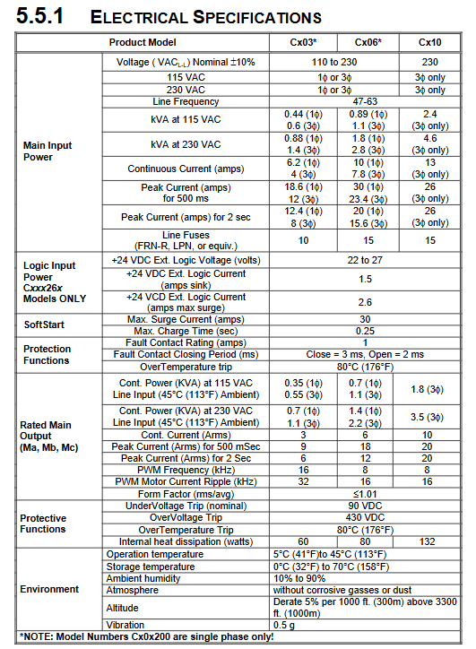
Core hardware specifications | Specification categories | Key parameters|
|Current output | Continuous current: 3A (Cx03)/6A (Cx06)/10A (Cx10); Peak current: up to 26A (500ms)|
|Power input | Voltage: 115VAC (single-phase/three-phase), 230VAC (single-phase/three-phase); Frequency: 47-63Hz|
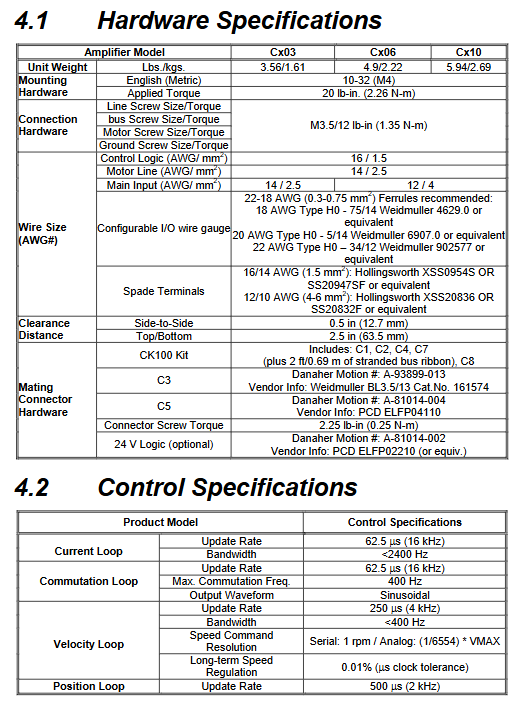
|Physical dimensions | Cx03: 67.3 × 163.0 × 36.6mm; Cx06: 83.3 × 216.0 × 33.7mm; Cx10: 99.1 × 244.0 × 33.7mm|
|Weight | Cx03: 3.56lbs (1.61kg); Cx06:4.9lbs(2.22kg); Cx10:5.94lbs(2.69kg) |
|Environmental requirements | Operating temperature: 5 ° C~45 ° C; Storage temperature: 0 ° C~70 ° C; Humidity: 10% -90% (no condensation); Protection level IP20|
Core control performance | Control loop | Update rate | Bandwidth | Resolution/accuracy related|
|Current loop | 16kHz (62.5 μ s) |<2400Hz | Suitable for three-phase motors, PWM frequency 8/16kHz | Speed loop | 4kHz (250 μ s) |<400Hz | Serial command resolution 1rpm, long-term stable speed accuracy 0.01%|
|Position ring | 2kHz (500 μ s) | – | Encoder input up to 3MHz, supports electronic gear function|
Installation and wiring specifications
Installation requirements
Installation method: NS 35/7.5 EN 50022 standard DIN rail installation, metal panel grounding (to ensure electromagnetic compatibility)
Heat dissipation spacing: Side to side spacing ≥ 12.7mm (0.5in), top to bottom spacing ≥ 63.5mm (2.5in)
Cabinet requirements: Metal shielded cabinet, maintain ventilation, avoid environmental temperature exceeding 45 ° C
Core wiring specifications
Cable separation: The distance between power lines (motor lines, power lines) and signal lines (feedback lines, I/O lines) is ≥ 20cm (8in), and they intersect at a 90 ° angle
Grounding requirements: Single point star grounding is used, and flat braided wire or copper bar is used for high-frequency grounding to avoid ordinary wires (excessive inductance)
Shielding treatment: Motor wires and feedback wires need to be shielded at both ends, and the shielding layer should be laid flat and grounded at the entrance of the cabinet. It is recommended to use Phoenix Contact shielding clips (such as SK8/SK14/SK20)
Key interfaces:
Power interface: L1/L2/L3 (three-phase input), GND (ground), B+/C (regenerative resistor)
Motor interface: MA/MB/MC (motor three-phase)
Feedback interface: C2 (motor feedback), C8 (remote encoder input)
I/O interface: C3 (user I/O, including analog input/output, fault relay, remote enable)
Communication interface: C1 (RS-232/RS-485), SERCOS port (fiber Tx/Rx, optional)
EMC Compliance Configuration
Input power filtering: An EMI filter (such as Cx03 adapted Filter Concepts SF7) needs to be configured and installed near the power entrance of the cabinet
Motor line filtering: Long cables need to be equipped with common mode chokes (such as Fair Rite 2643665702) to avoid high-frequency interference
I/O line filtering: 24V power line, remote enable line need to be equipped with ferrite core (such as Fair Rite 2643167251)
Communication and software configuration
Communication mode configuration
Serial communication (RS-232/RS-485):
Baud rate: 9600/19200bps (set through DIP switch 6)
Address setting: DIP switches 1-5 are used to set multiple machine addresses (0-31), with address 0 indicating single device mode
Connection method: RS-232 supports point-to-point connection, RS-485 supports multi machine cascading (up to 31 units)
SERCOS fiber optic communication (optional):
Transmission rate: 2M/4Mbps (DIP switch 6 setting)
Address setting: DIP switches 1-5 are used to set the address (0-31), with 0 indicating repeater mode
Cable requirements: 1mm plastic optical fiber, attenuation ≤ 0.18dBm/m, maximum transmission distance 71.4m (high-power mode)
MOTIONLINK software features
Core functions: device configuration, motor parameter loading, control mode selection, automatic tuning, real-time monitoring, fault viewing
Operation process:
Install software (requires Windows system, 16MB RAM)
Connect devices through serial port
Complete motor configuration, control mode selection, and parameter tuning using Startup Wizard
Save parameters to EEPROM or SSV file (for backup/recovery)
Advanced features: direct command sending in terminal mode, oscilloscope function to record motion curves, batch configuration of multiple devices
System operation and control
Detailed explanation of control mode
Current/torque mode (OPMODE 2/3): receives ± 10V analog signals or serial T commands, current loop bandwidth<2400Hz, supports torque compensation
Speed mode (OPMODE 0/1): Receive ± 10V analog signals, serial J commands or I/O triggers, speed range 0~VLIM (configurable), supports S-curve acceleration and deceleration
Position mode (OPMODE 4/8): Supports electronic gears, pulse/direction counting, encoder tracking, positioning accuracy depends on feedback devices, supports zero return function
Key operational processes
Power on self-test: After the device is powered on, a self-test is performed, and the status display flashes. After all segment codes are displayed, the running mode (0-8) is displayed
System enablement: Must meet ACTION=READY × REMOTE × DIPEN, READY=DRIVE OK × SWEN (no fault+software enablement)
Feedback calibration: The sine encoder needs to perform SINInitiat calibration, and the rotary transformer achieves high-precision sampling through software RDC conversion
protection function
FoldBack protection: The exponential decay of current to continuous current value (ICONT) starts 1/2 second after driving overload
Motor thermal protection: Monitor the motor thermoelectric signal through THERM variable, display “H” and disable when overheating occurs
Other protections: overvoltage (430VDC trip), undervoltage (90VDC trip), overcurrent, overtemperature (80 ° C trip)
Troubleshooting and Maintenance
Classification and Handling of Fault Codes
Fatal malfunction (such as Err1: power level overheating, displaying “t”): Power off and restart are required to investigate heat dissipation or load
Non fatal faults (such as Err20: unknown command): can be cleared through software and the command format can be checked
No message fault (such as hardware limit triggering, displaying “L”): I/O wiring or limit switch status needs to be checked
Common troubleshooting tools
MOTIONLINK status screen: View fault history (FLTHIST), device status (Status)
I/O screen: Check the output status of limit switches, thermostats, and encoders
Monitoring screen: Compare parameters such as current (I/IA/IC), speed (V/VCMD), position (PFB/PE), etc
Maintenance and Upgrade
Daily maintenance: maintenance free, use dry and lint free cloth for cleaning, prohibit the use of cleaning agents
Firmware upgrade: Download the firmware (. emb file) through the RS-232 port using the Ignite. exe tool, and restart the device after the upgrade
Repair restrictions: Only manufacturers or authorized engineers can repair, unauthorized repairs may void the warranty