KEBA KeControl C1 CP 03x series CPU module
Product Overview
KEBA KeControl C1 CP 031/Z, CP 033/Y, and CP 033/Z are the central processing unit modules of the K2-200 module system, designed for industrial automation scenarios. The core advantages are the use of CPU types optimized for computation to achieve cost reduction, the installation of industry-specific I/O boards, and the use of mature PC components to ensure availability and reliability. The core configuration of the module is a 400MHz Motorola PowerPC processor, 128 MB SDRAM internal memory, and 512 kB battery buffered SRAM, running the VXWorks operating system; The firmware and application data are stored on a Type 1 Compact Flash memory card, which can be connected to Kemro series graphic panels via an LVDS graphical interface. The startup/running status is displayed through a 7-segment diagnostic display screen and status LED, and the corresponding working status can be accessed through a matching operation switch.
General Technical Parameters
The general parameters are the basic configuration of the entire series of modules, with only model differences in power consumption. The core values are shown in the table below:
General value of parameter item, model differentiation value
Rated supply voltage 24 V DC (front power supply)-
Supply voltage range 19.2 V -30 V (compliant with EN 61131-2)-
Maximum power consumption – CP 031/Z: 125 W; CP 033/Y:125 W; CP 033/Z:153 W
Overvoltage level II-
Protection level (EN 61131-2) III-
No electrical isolation-
External replaceable unit fan for heat dissipation-
Working temperature+5 ℃ -+55 ℃-
Storage temperature -40 ℃ -+70 ℃-
Working humidity 10% -95% (no condensation)-
Vibration/impact resistance in accordance with EN 61131-2-
Detailed configuration of I/O interface
The module is equipped with an industry optimized I/O board, supporting multiple types of inputs and outputs such as digital, analog, speed, and temperature. There are core differences in the number/specifications of interfaces for different models, and the key parameters for each type of interface are as follows:
1. Digital input
Quantity: CP 031/Z/CP 033/Y32 channels, CP 033/Z48 channels (including DI/VI0 and DI/VI1 speed inputs)
Type: Type 1 (compliant with EN 61131-2), without electrical isolation
Voltage range: “1” is 15 V ≤ UH ≤ 30 V, “0” is * * -3 V ≤ UL ≤ 5 V**
Performance: Minimum update cycle of 1 ms, green LED status display
2. Speed input (DI/VI0, DI/VI1)
Frequency range: minimum 0.5 Hz, maximum 100 Hz
Counter resolution: 16 bits
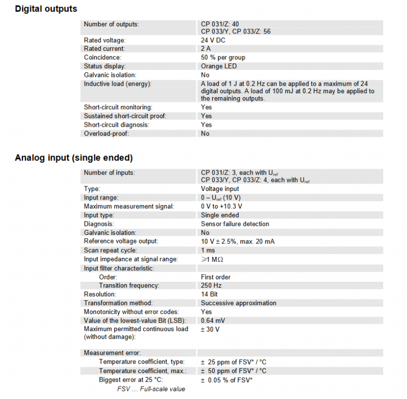
3. Digital output
Quantity: CP 031/Z40, CP 033/Y/CP 033/Z56
Rated parameters: 24 V DC/2 A, no electrical isolation, orange LED status display
Load characteristics: 50% overlap between each group; 24 channels can be connected to 1 J/0.2Hz inductive load, while the rest can be connected to 100 mJ/0.2Hz inductive load
Protection: Supports short circuit monitoring, short circuit diagnosis, continuous short-circuit resistance, no overload protection
4. Simulate single ended input
Quantity: CP 031/Z3, CP 033/Y/CP 033/Z4 (all with Uref reference voltage)
Type: Voltage input, 0-10 V range, maximum measurement signal 0 V -+10.3 V, no electrical isolation
Performance: 14 bit resolution, successive approximation conversion, 1 ms scan cycle, input impedance ≥ 1 M Ω, LSB of 0.64 mV
Diagnosis: Supports sensor fault detection
5. Simulate differential input
Quantity: CP 031/Z2, CP 033/Y/CP 033/Z4 (with Iref reference current)
Core parameters: Consistent with single ended input, with additional support for * * ± 11 V * * common mode control and 60 dB common mode suppression
6. Analog voltage output
Quantity: CP 031/Z5, CP 033/Y/CP 033/Z6
Type: Single ended, ± 10 V output range, no electrical isolation
Performance: 12 bit resolution, LSB of 5.02 mV, 1 ms conversion/update cycle, minimum load resistance of 1 k Ω, maximum capacitive load ≤ 10 nF
Accuracy: Differential nonlinearity ≤± 1 LSB, full-scale setup time ≤ 200 μ s
7. Simulate current output
Quantity: CP 031/Z/CP 033/Y3, CP 033/Z4
Type: PWM dual position control (dynamic hysteresis), 38 V ± 5% PWM output voltage
Performance: Maximum switching frequency of 20 kHz, typical 5 kHz (load dependent), output current of 1 A ± 5%, minimum hysteresis of 80 mA, maximum ripple current of 230 mA
Load/power: minimum load inductance of 20 mH, maximum load resistance of 100 Ω; Single channel power 25 W, total power of 4 channels 90 W
8. Temperature input
Quantity: CP 031/Z7, CP 033/Y/CP 033/Z8, with electrical isolation (707 V DC)
Supports thermocouples: J (Fe CuNi), K (NiCr Ni), L (Fe CuNi), with different measurement ranges for each type
Performance: 14 bit resolution, integral measurement principle, 100 ms measurement time, input impedance ≥ 10 k Ω
Compensation: Supports internal/external temperature compensation, and the external TE 220/A sensor can minimize the error to ± 0.5 ℃ (typical)
Accuracy: The maximum absolute deviation at 25 ℃ is 1.5 ℃, and the working deviation is ± 1% of the measured value or ± 25 ℃ (whichever is greater)
Communication interface
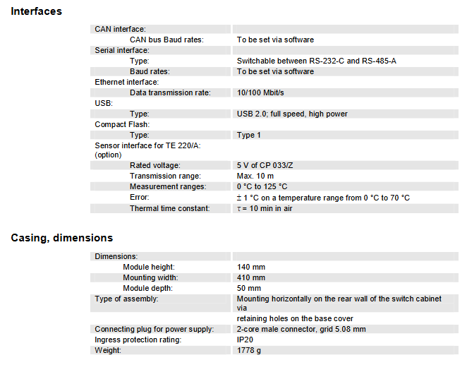
The module is equipped with multiple types of industrial communication interfaces to meet the communication needs of different scenarios. The key parameters are as follows:
CAN interface: baud rate software setting, supports CANopen specification, can achieve cluster decentralization and long-distance transmission of K2-200 module system
Serial interface: switchable between RS-232-C and RS-485-A, baud rate software setting
Ethernet interface: data transmission rate of 10/100 Mbit/s
USB interface: USB 2.0 (full speed, high power)
Optional interface: TE 220/A sensor interface (CP 033/Z only, 5V power supply, maximum transmission distance 10 m, measurement range 0-125 ℃)
Graphic interface: LVDS interface, dedicated to connecting Kemro series graphic panels
Mechanical and installation parameters
Dimensions: Module height 140 mm, installation width 410 mm, module depth 50 mm
Installation method: Install horizontally on the back wall of the switchgear through the fixing hole of the base cover plate
Connector: Powered by a 2-core male connector (with a grid spacing of 5.08mm); RM 5.08 plug-in terminal block with gold-plated contacts for temperature input
Protection level: IP20
Weight: 1778 g
Core functional characteristics
Diagnostic function: The entire series of I/O interfaces support sensor fault detection, digital output supports short circuit diagnosis, and 7-segment display screens achieve visual operation status
Protection function: The digital output has continuous short-circuit protection and short-circuit monitoring, and the power supply and interface comply with industrial standard overvoltage/protection levels
Compatibility: Seamless compatibility with K2-200 module system, Kemro graphic panel, TE 220/A temperature sensor
Stability: Using mature PC components and equipped with battery buffered SRAM to ensure data and operational stability