KEBA FM 299/A GA1060 fieldbus main module
Product Fundamentals and Safety Requirements
Product positioning: FM 299/A is the fieldbus main module of K2-200 automation system, designed specifically for Sanyo Denki’s drive bus. A single K2-200 control CPU can run up to 2 of these modules.
Installation attribute: The module is an open device that must be installed inside the control cabinet and must comply with all safety regulations in the K2-200 Automation System Project Engineering Manual.
Operation safety: The power must be turned off before inserting or removing the module, otherwise it may damage the module or the control system due to abnormal signal status.
Power supply and power consumption: 5V logic power supply is provided by K-Bus, with a maximum power consumption of 1.0 W and a safety level of III (compliant with EN 61131-2 standard).
Compliance standards: The module has passed UL 508 certification (UL listed) and complies with the programmable controller product standards IEC 61131-1:2003 and IEC 61131-2:2003.
Module configuration method
The core of module configuration includes module naming, GA1060 bus parameters (name+cycle time), and parameter configuration for supporting Sanyo QSE series drivers. It supports two configuration methods and requires K-Bus address settings, as follows:
Configuration Method 1: Kemro.manager Visual Configuration
All modules of K2-200 system and Sanyo QSE series converters/drivers can be uniformly configured;
After selecting the FM 299/A module, the software will automatically create a bus connection column for associating driver devices;
After all modules and parameter configurations are completed, the software will automatically generate the required cfg configuration file.
Configuration method 2: Text editor to edit cfg files
The FM 299/A module and GA1060 bus only require configuration of name and cycle time, without any other special parameters;
The cfg file needs to simultaneously configure the driver devices (such as QSE drivers) on the GA1060 bus, including parameters such as address, working mode, unit conversion factor, register group, etc;
High user privileges can configure optional parameters to define system feedback when a module is unavailable (0=no prompt, 1=error, other=warning).
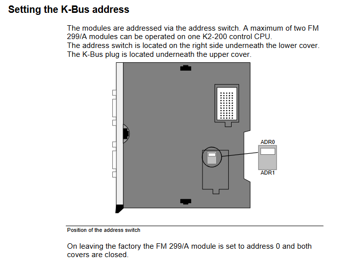
K-Bus Address Setting
The module implements K-Bus addressing through an address switch, which is located under the lower cover on the right side of the module, and the K-Bus plug is located under the upper cover;
The default factory address is 0, and a single CPU can support up to 2 modules. The corresponding address can be set as needed.
Wiring and GA1060 Bus Specification
The core communication interface of the module is the GA1060 bus, which must strictly comply with shielding, wiring, and topology specifications to ensure communication stability. The key requirements are as follows:
SDC Bus Interface (GA1060) Hardware Specification
Connector: 9-pin D-SUB socket connector (fully conductive shell), the cable shielding layer needs to be connected to the plug shielding cover plane, without the need for additional shielding grounding;
Pin definition:
|Pin | Function | Pin | Function|
|Pin1 | GA1060 Bus+| Pin3-8 | GND (Ground)|
|Pin2 | GA1060 Bus – | Pin9 | n.c. (empty foot)|
Cable requirements: Use shielded twisted pair cables with characteristic impedance of 100-120 Ω, GA1060 Bus+and Bus – must be the same pair of twisted pair cables; Multi core twisted cables can also be used, ensuring that the positive and negative wires of the bus are twisted together.
Wiring requirements
The signal/data lines of non Kemro control systems cannot be wired together with the system’s own signal lines;
Shielded signal lines, data lines, and low-voltage power supply lines of the system with two ends can be wired parallel to each other or parallel to the power supply lines.
Bus topology requirements
The GA1060 bus is a bus system that must be connected to a bus terminal board (BT) at both ends. The terminal board needs to be soldered with a 120 Ω resistor between Pin1 and Pin2;
The FM 299/A module can be connected to any position on the bus (end/middle), and the CN1 and CN2 interfaces of the module have no position restrictions;
The total length of the bus cannot exceed 10 meters, and the spacing between nodes can be freely set;
If the module is connected to one of the terminal boards on the bus, its idle interface must also be connected to the terminal board.
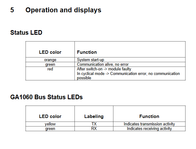
Operation status and display
The front of the module is equipped with a main status LED and a GA1060 bus communication LED, which enable visual diagnosis of operation and communication status through different colors/markings. The specific functions are as follows:
Main status LED
|LED color | working status|
|Orange | System startup in progress|
|Green | Communication is normal and there are no faults|
|Red | After startup=module failure; Communication failure in loop mode, unable to communicate|
GA1060 bus status LED
|LED color | identification | function|
|Yellow | TX | Indicates bus data transmission activity|
|Green | RX | Indicates bus receiving data activity|
Core technical parameters
The FM 299/A module is compact in size and has low power consumption. The core technical parameters are shown in the table below:
Category parameter item numerical value
Power supply and power consumption logic power supply 5V (via K-Bus)
Maximum power consumption 1.0 W
Communication interface GA1060 bus transmission rate 10 Mbit/s
The maximum length of the bus is 10 meters (between the first and last nodes)
Physical dimension module height 120 mm
Installation depth of 100mm
Front panel width 22.5 mm
Total width including K-Bus plug 32.5 mm
Weight -130 g
Safety and Certification Safety Level III (EN 61131-2)
Certification standards UL 508, IEC 61131-1:2003, IEC 61131-2:2003
The maximum number of modules per CPU is 2