HITACHI frequency converter Cs-H100 series
Installation and wiring
1. Installation requirements
Environmental conditions:
Temperature: -10~50 ℃ (40~50 ℃ needs to be downgraded for use); Humidity: ≤ 95% RH (no condensation)
Altitude: ≤ 1000m (with a decrease of 1% for every 100m increase above 1000m, up to a maximum of 2000m)
Avoid: direct sunlight, dust, corrosive gases, vibration (≤ 0.6g)
Installation specifications:
Method: Vertically installed on non combustible metal walls, with fixing screws bearing the weight of the body
Space: Reserve ≥ 10cm of heat dissipation space on the top, bottom, left, and right sides, and add insulation deflectors for multi-layer installation
Inside the control cabinet: Reasonable layout of ventilation fans to avoid hot air circulation
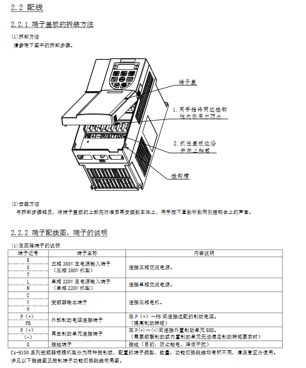
2. Wiring specifications
Main circuit terminal description
|Terminal markings | Function | Wiring requirements|
|R/S/T (three-phase)/L/N (single-phase) | Power input | 380V for three-phase or 220V for single-phase, with residual current circuit breaker required|
|U/V/W | Motor output | Connecting three-phase motors, if the wiring length exceeds 100m, an output reactor needs to be added|
|P (+)/PB | Brake resistor connection | Select the minimum resistance value (13.6~300 Ω) according to the model, wiring ≤ 5m|
|G | Grounding | Independent grounding, wire diameter ≥ power wire|
Control circuit terminal:
7.5kW and below: 5-way DI, 1-way AI, 1-way AO, 1-set relay output
11kW and above: 6-way DI (including 1 high-speed pulse input at 100kHz), 2-channel AI, 2-channel AO, 2-channel relay output
Recommended wire diameter and accessories
|Inverter model | Power line (mm ²) | Control return line (mm ²) | Grounding wire (mm ²) | Recommended accessories|
|CsH100-004SF (0.4kW) | 2.5 | 1.5 | 1.5 | Braking resistance ≥ 220 Ω/100W|
|CsH100-110HF (11kW) | 6.0 | 1.5 | 6.0 | Input Reactor, Noise Filter|
|CsH100-220HF (22kW) | 10 | 1.5 | 10 | Output reactor, braking resistor 13.6 Ω/3.7kW|
Operation and Handling
1. Four core operating modes
table
Applicable scenarios for setting key parameters of operation mode control source
Operator Control Body Operator F0-04=0 (operator command), F0-06=1 (preset frequency) Single machine debugging, manual operation
Terminal control DI/AI terminal F0-04=1 (terminal command), F0-06=2 (AI1 given) External switch/potentiometer control
Multi speed control, multi speed terminal F0-06=4 (multi speed), FC-00~FC-15 set speed, fixed speed switching (such as pipeline)
485 communication control upper computer (PLC, etc.) F0-04=2 (communication command), F0-06=7 (communication given) centralized control, multi device linkage
2. Key operational procedures
Motor parameter self-tuning (recommended for vector control):
Set motor nameplate parameters (F4-01~F4-06: power, voltage, current, etc.);
Select self-tuning mode (F4-00=1 static/2 rotation);
Press the RUN button on the operator to start, and it will automatically adjust for up to 2 minutes to update parameters such as motor inductance and resistance.
Trip reset:
After the fault occurs, the frequency converter cuts off the output and displays a fault code;
After investigating the cause, press the STOP/RESET button or reset through the DI terminal (assigned the “fault reset” function);
If the trip still occurs, power off for 10 minutes (confirm that the bus voltage is<45V) before restarting.
485 communication function
1. Communication specifications
table
Project parameter setting method
Protocol Modbus RTU (Slave) Fixed
Baud rate 300/600/1200~38400bps F8-00 setting (default 9600bps)
Data format: 8-bit data bit, 1/2 stop bit, no/even/odd parity F8-01 setting (default 8, N, 1)
Communication address 0~247 (0 is the broadcast address) F8-02 setting (default 1)
Maximum Connection Number 247 Operator Settings
2. Core communication functions
Register read and write:
Read register (03h): Read up to 12 at a time, such as reading the set frequency (address 1001h) and output current (1005h);
Write register (06h): Write one at a time, such as writing forward instruction (address 2000h=0001h), set frequency 45.00Hz (address 9000h=1194h).
Common register addresses
|Register Address (hex) | Function | Read/Write Properties|
|1001 | Set frequency (0.01Hz) | Read|
|1005 | Output current (0.1A) | Read|
|2000 | Control command (forward/reverse/stop) | Write|
|8000 | Fault Status | Read|
Fault handling and maintenance
1. Common fault codes and countermeasures
table
Fault code, fault name, core cause, handling measures
Err04 acceleration overcurrent acceleration time is too short, motor short circuit, load sudden change 1. Increase acceleration time (F0-23); 2. Check the insulation of the motor; 3. Check the load
Err09 deceleration overvoltage, short deceleration time, no brake resistor connected. 1. Increase deceleration time (F0-24); 2. Configure braking resistors; 3. Activate overexcitation braking
Err14 motor overload load is too large, and the overload protection gain is improper. 1. Reduce the load; 2. Adjust F9-01 (overload protection gain); 3. Check the heat dissipation of the motor
Err27 communication fault wiring error, parameter mismatch 1. Check 485+/485- wiring; 2. Confirm that the baud rate/address is consistent; 3. Add a terminal resistor (120 Ω)
2. Maintenance and upkeep
Daily maintenance:
Inspection: Motor sound/vibration, fan operation, ambient temperature;
Cleaning: Remove dust and oil stains from the surface of the frequency converter and fan.
Regular check (recommended every 6 months):
Tighten the wiring terminals, check the smoothness of the air duct, and test the insulation of the main circuit (500V megohmmeter).
Replacement of lifespan components:
Cooling fan: 2-3 years (to be replaced in case of abnormal noise/stoppage);
Electrolytic capacitor: 4-5 years (to be replaced in case of leakage/bulging).
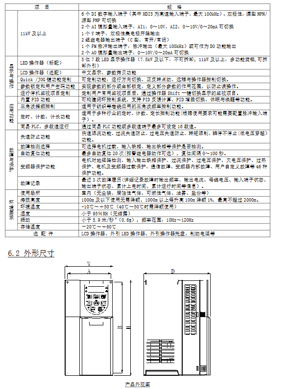
Product specifications and core functions
1. Core electrical specifications
table
Project specification parameters
Suitable motor power: 0.4kW~22kW (SF single-phase model), 0.75kW~22kW (HF three-phase model)
Input voltage: single-phase 220V (-15%~+10%), three-phase 380V (-15%~+10%)
Output frequency range 0~590Hz (resolution 0.01Hz)
Rated overload capacity 150% rated current/60s, 180% rated current/6s
Control mode V/F control (constant torque/reduced torque), sensorless vector control
Starting torque asynchronous motor vector control: 180% @ 0.5Hz
2. Core application functions
Basic functions: multi speed (16 speed), S-shaped acceleration and deceleration, dead zone for forward and reverse rotation, frequency jump (avoiding resonance);
Advanced features: PID control (closed-loop regulation), swing frequency control (textile winding), simple PLC (16 segment program), master-slave control, sleep wake-up;
Protection function: 46 types of protection (overcurrent, overvoltage, undervoltage, overload, phase loss, short circuit to ground, etc.), supporting automatic fault reset (up to 20 times).
Parameter Setting System
Parameter group classification (8 groups in total):
F0~FF: Basic functions (control mode, operation command source, acceleration and deceleration time);
H0~H3: Second motor parameters (independently set two sets of motor parameters);
L0~L6: Enhanced functions (master-slave control, brake control, sleep function);
U0~U1: Monitoring parameters (fault records, operation status monitoring).
Parameter operation optimization:
Supports 3 menu modes (basic/user customized/initial value change);
Users can customize 31 commonly used parameters (L1 group) and support password locking (F7-49).