HITACHI SAM PS100 series pressure based PI mass flow controller
Product Overview
Product positioning: PS100 series is a new type of mass flow controller (MFC) developed by Hitachi, which is mainly used in semiconductor manufacturing equipment. It is designed for flow control requirements of thermal degradation gases and corrosive gases (such as Cl ₂, BCl ∝). With a non heating architecture and pressure insensitivity, it achieves long-term stable flow measurement and control.
Core value: Solve the performance degradation problem of traditional MFCs in high temperature and corrosive environments, while balancing high precision, high-speed response, and high durability, and adapting to scenarios such as frequent start stop and multi gas switching in semiconductor processes.
Core Features and Advantages
Detailed description of key characteristics in feature classification
Measurement architecture without heating pressure measurement 1. Reduce the residual reaction of thermally degraded gases in the gas path; 2. Reduce the corrosion of corrosive gases under high temperature and humidity conditions; 3. Long term stable measurement and control
The pressure insensitive function improved by pressure adaptability: 1. Upstream pressure fluctuations are offset by mechanical regulators; 2. Downstream pressure fluctuations are compensated by control valves; 3. The pressure (P1/P2) in the laminar flow device area remains stable, ensuring the accuracy of flow control
High precision control performance ± 1% S.P. (N ₂, 10-100% range), ± 0.1% F.S. (0.5-10% range); Linearity ± 0.5% F.S; Repeatability ± 0.25% F.S
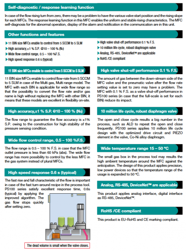
Control performance, high-speed response, stable time<0.8s, typical value 0.6s; quickly cut off gas after zero setting, suitable for fast switching process
Durable and long-lasting valve adopts piezoelectric actuator+cobalt nickel alloy diaphragm, optimized driving circuit, valve life reaches 10 million times, suitable for frequent start stop processes such as ALD
11 BIN specifications with multiple gas and range functionalities, flow range of 5 SCCM~5 SLM; Support gas type/flow range switching, no need to replace MFC
Intelligent function self diagnosis/response learning 1. Response learning: unify the flow rise characteristics (solve the differences in different MFC startup positions/slopes); 2. Self diagnosis: abnormal operation detection, alarm display, and communication notification
Sealed and compatible, corrosion-resistant, and compliant. The contact material for the gas circuit is 316L stainless steel PCTFE、 Nickel cobalt alloy; Compliant with EU RoHS and CE certification
Key technical specifications
Specific parameters of specification items
Flow range (N ₂ equivalent) 5 SCCM~5 SLM (11 BINs, Multi 0~Multi 10)
Flow control range 0.5~100% F.S. (outlet pressure<60kPa abs)
Accuracy (N ₂) 10-100% Range: ± 1% S.P; 0.5-10% range: ± 0.1% F.S
Stability time (SEMI) ™ E17-91)<0.8s (typical value<0.6s)
Valve shut-off performance<0.1% F.S. (set according to BIN full range)
Working pressure (inlet) conventional pressure type: 230~600kPa (abs); Low vapor pressure type: 140~250kPa (abs)
Working pressure (outlet) vacuum~60kPa (abs)
Working temperature 15~50 ℃ (gas temperature needs to be consistent with ambient temperature)
Gas path material 316L stainless steel PCTFE、 Nickel cobalt alloy
Joint specification 92mm 1.125 “Cseal/WSeal ®
Surface roughness electrolytic polishing (joint/sensor/base) Ra=0.2 μ m; Mechanical processing Ra=0.8 μ m
Weight 1.1kg
Interface and electrical connection
1. Interface type and connector
Interface type, connector specifications, core pin functions
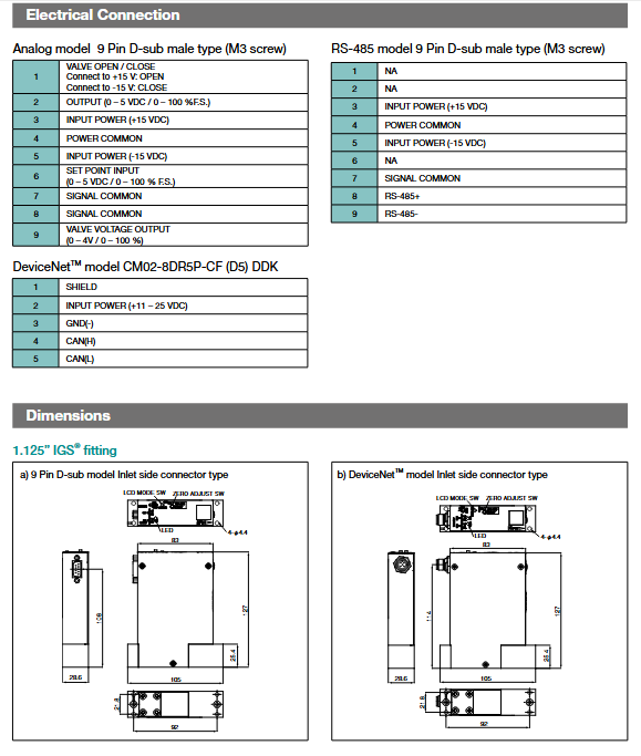
Analog interface 9-pin D-sub male head (M3 screw) power supply (+15V/-15V), set value input (0-5VDC), flow output (0-5VDC), valve switch control
RS-485 interface 9-pin D-sub male head (M3 screw) power supply (+15V/-15V), RS-485+/-, signal common terminal
DeviceNet ™ Interface CM02-8DR5P-CF (D5) DDK power supply (11-25VDC), CAN (H)/CAN (L), shielded wire
2. Power requirements
Interface type, power parameters
Analog/RS-485+15VDC ± 4% (90mA), -15VDC ± 4% (60mA)
DeviceNet ™ +11~25VDC(300mA~150mA)
Model coding rules and examples
1. Model code structure
Model prefix, interface type, joint position, sealing type, valve type, joint specification, fixed code, optional code, flow range
PS100 A=simulation; D=DeviceNet ™; L=RS-485 T=top; U=inlet side (excluding RS-485) M=metal seal C=normally closed BA1=1.125 “Cseal; BW1=1.125” Wseal ® 0 NNN Multi 0~Multi 10 (corresponding to 5 SCCM~5 SLM)
2. Model Example
Model: PS100ATMCBA10NNN Multi-5
Meaning: Pressure type MFC+analog control+top connector+9-pin D-sub+metal seal+normally closed piezoelectric valve+1.125 “Cseal connector+no options+flow range of 200 SCCM