GE Fanuc i series control operation panel
Core types of operation panel
The manual includes two types of operation panels: North American type and distributed I/O type, both of which are compatible with i-series CNC. The core parameters are shown in the following table:
Panel type, core model, physical dimensions, key characteristics, certification/adaptation
North American model 44A739025 (standard)
44A739026 (customized/with MPG) 520/400mm × 180mm × 90mm (50mm without connecting unit) ① Supports LED/incandescent backlight and cannot be mixed;
② Equipped with emergency stop, rotary switch, and memory protection key;
③ Pre wired, equipped with A20B-2002-0470 mounting bracket;
④ Supports up to 3 MPG UL certifications and CE compliance
Distributed I/O type A02B-0236-C140 (520mm, full keyboard)
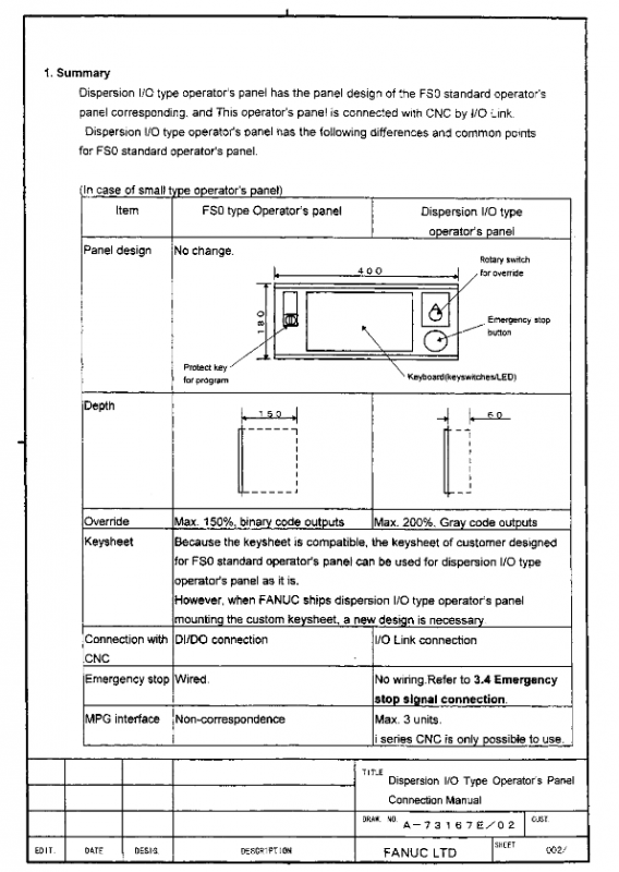
A02B-0236-C141 (400mm, small keyboard) 520/400mm × 180mm × 60mm ① membrane keyboard+embedded LED;
② Built in I/O connection unit, supporting 3 MPGs;
③ Magnification switch outputs Gray code (maximum 200%);
④ Lathe (T)/machining center (M), English (R)/symbol (S) version CE certification, compatible with FS0 panel design
Additional features of North American panel: Provides customized services, optional with/without MPG, add/remove buttons, equipped with LED upgrade kit (44A736871-G01/G02), emergency stop button needs to be wired to meet safety requirements.
Connection unit/IO module (three cores)
To adapt to the I/O interaction between the operation panel and CNC, the manual provides three connection units, all of which are source type outputs and electronic fuse protection. They communicate through I/O Link, and the core parameters are shown in the following table (key models/points in bold):
Model I/O point count input type output type MPG support core features
A20B-2002-0470 72DI/56DO 16 ordinary DI+56 matrix DI (8 × 7) 56 24V source type DO up to 3 ① matrix DI needs to be connected in series with diodes to prevent short circuits;
② Exclusive matching for North American panels;
③ DOCOM pin single load ≤ 0.7A
A20B-2002-0520 48DI/32DO 48 channel non matrix DI (fully independent) 32 channel 24V source DO up to 3 channels ① No matrix input, simpler wiring;
② Can be used independently as an I/O module
A20B-2002-0521 48DI/32DO 48 channel non matrix DI (fully independent) 32 channel 24V source type DO Wuwei 0520 without MPG version, all other specifications are completely the same
Common requirement: The 24VDC power supply of the three modules must be connected/disconnected before/at the same time as the CNC is powered on, and disconnected/at the same time after power off, otherwise it will trigger the CNC communication alarm.
Core installation and wiring specifications
(1) Power supply connection (mainly 24VDC ± 10%, 15i special)
16i/18i/21i CNC&Power Mate i D/H: No built-in power supply, requires external 24VDC power supply, recommended cable kit 44C742962-G01, North American panel built-in 24VDC switch (maximum 8A), can synchronously control CNC and peripheral equipment.
15i CNC: Comes with a 200VAC power supply and can provide 24VDC on its own. It requires a dedicated cable kit 44A739097-G01. The ON/OFF button on the panel is directly connected to the 15i power module without the need for a built-in switch circuit on the panel.
Safety requirements: Reversing the polarity of 24VDC can damage the CNC inverter board. The wiring should be properly grounded and anti-interference. It is recommended to provide separate power supply for external I/O to avoid load interference.
(2) MPG (Manual Pulse Generator) connection
Quantity supported: Three devices with MPG interface (distributed I/O panel, 0470, 0520) all support up to 3 MPGs, and are only available for i-series CNC.
Cable requirements: Recommended cable A66L-00001-0286, with a maximum length of 50m (theoretical 76.75m) for a single MPG, 38.37m for two MPGs, 25.58m for three MPGs, and a voltage drop of ≤ 0.2V.
Signal requirements: The third-party MPG must meet the requirements of HA/HB pulse period ≥ 200 μ s, high level ≥ 3.7V, and low level ≤ 1.5V.
Address occupancy: The MPG interface occupies fixed DI addresses Xm+12~Xm+14, which are directly processed by CNC software and cannot be used for user ladder diagrams.
(3) Emergency stop (ESP) wiring
All emergency stops of panels/modules need to be wired by themselves. The manual provides three wiring schemes, and it is recommended to allocate the emergency stop signal to a fixed DI address of Xm+0.0~Xm+0.7 (0470)/Xm+2.0~Xm+2.7 (distributed I/O type).
Safety requirements: The emergency stop signal is prohibited from being assigned to the matrix DI area and must use normally closed contacts to ensure that the emergency stop is triggered when the wire is disconnected.
(4) Cables and connectors
Special cables: extension cable for North American panel (44A739032-G01, 1m), 15i special power supply line (44C742962-010), MPG special line (A02B-0120-K841/848/847, 7m).
Connector specifications: Recommended power connectors are A02B-0120-K323/K324, I/O ribbon connectors are A02B-0120-K342, and MPG connectors are A02B-0120-K303.
I/O Mapping and Signal Specification
(1) DI/DO mapping rules
Grouping requirements: DI must be grouped by 16 bytes, DO by 8 bytes, as MPG (Xm+12~14) and DO alarm (Xm+15) are fixed addresses and require 16 bytes of DI space.
Address allocation: Distributed I/O panel DO is Yn~Yn+70470 module DO is Yn~Yn+60520/0521 module DO is Yn~Yn+3, the specific address can be customized, but it needs to avoid CNC fixed processing addresses.
Alarm address: The DO overload/overheating alarm is fixedly mapped to Xm+15 and triggered by byte (such as Xm+15.0 corresponding to Yn+0). After triggering, the corresponding DO byte is closed and needs to be restored after troubleshooting.
(2) Signal Electrical Specification
DI signal: Ordinary DI is 24V type, with a capacity of DC30V/16mA, leakage current ≤ 1mA (26.4V), and voltage drop ≤ 2V; matrix DI is 5V type, with a capacity of DC6V/2mA and voltage drop ≤ 0.9V.
DO signal: source type output, maximum load of 200mA per channel (instantaneous), saturation voltage drop ≤ 1V (at 200mA), leakage current ≤ 20 μ A, can be connected in parallel with two channels (maximum 400mA).
Delay time: DI reception delay ≤ 2ms, DO drive delay ≤ 50 μ s, requiring the addition of I/O Link communication delay (≤ 2ms) and ladder diagram scanning period.
Maintenance and troubleshooting
(1) Vulnerable parts and replacement
North American panel renewal parts: button (44A717186-014), ON/OFF button (44A717186-016), rotary switch (44A724658 series), MPG (A860-0202-T001), LED/incandescent light (44A717186-042/051-053).
Tools and kits: Lamp bead disassembly tool (44A739089-G01), LED upgrade kit (44A736871-G01/G02), emergency stop contact accessories (44A724659-006/007).
Jumper setting: The JP1 jumper for North American panels needs to be adjusted according to the backlight type (incandescent bulbs inside the rectangular frame, LEDs outside the frame), and cannot be mixed, otherwise it will cause backlight abnormalities.
(2) Common fault handling
DO alarm: Xm+15, position 1 indicates overload/overheating of the corresponding DO byte. Load short circuit and grounding need to be checked, and the fault will be automatically restored after troubleshooting.
MPG no signal: Check the cable voltage drop (≤ 0.2V), wiring polarity, and CNC address mapping (Xm+12~14) to ensure that the MPG interface is the unit closest to the CNC on the I/O Link.
Communication alarm: Check whether the 24VDC power supply (synchronized with CNC on/off), I/O Link connector (HIROSE F130-20S-CV7 disabled), and panel/module address conflict.
Matrix DI error: If more than 3 buttons are pressed simultaneously, anti misoperation processing should be done through a ladder diagram. The matrix DI needs to be connected in series with diodes, otherwise signal errors will occur.
Environmental and safety regulations
Environmental requirements: Operating temperature of 0-58 ℃, storage/transportation of * * -20~60 ℃ * *, normal humidity of ≤ 75%, short-term (within 1 month) ≤ 95%, vibration ≤ 0.5G, to be used in a closed cabinet, with a temperature rise of ≤ 10 ℃ inside the cabinet.
Safety regulations:
The 24VDC switch power supply of the North American panel has not been cut off by CNC’s Control Off logic, please refer to the circuit diagram of the machine tool factory;
Disassembling incandescent lamps requires the use of specialized tools, and the use of conductive tools (such as pointed nose pliers) is prohibited to avoid short circuits triggering I/O errors;
All grounding must comply with FA industry standards, and the wiring must be well treated for anti-interference to avoid electromagnetic interference causing signal abnormalities.