Emerson Ovation I/O System
General Technical Specifications
Specific parameters for standardized categories
Environmental working temperature: 0~60 ℃ (32~140 ° F); Storage temperature: -40~85 ℃ (-40~185 ° F); Humidity: 0~95% (no condensation)
Electrical isolation channel and logic room: 1000V AC/DC (1 minute); Differential input channels: 1000V AC (some modules)
Power supply requirement: Main power supply: 24VDC ± 10%; Auxiliary power supply: 24VDC/48VDC (some modules), external power supply must comply with noise specifications (500Hz~10kHz ≤ 2.2mV RMS)
Diagnostic identification criteria LED: P (green, power supply normal), C (green, communication normal), E (red, external fault), I (red, internal fault), CH1~CHn (channel status)
Installation features: DIN rail installation, module supports hot swapping, basic unit can accommodate 2 standard modules, terminal block with test points and spare fuses
Noise suppression technology
Noise classification: Divided equally into high (H class, ≥ 110VAC), medium (M class,>48V), low (L class, 24/48V), and extremely low (Q class, analog signal).
Suppression measures:
Wiring: Shielded twisted pair cables are used for analog signals, multi-core shielded cables are used for digital signals, and strong and weak current are separated for wiring.
Grounding: Single point grounding of the shielding layer (at the cabinet or on-site equipment end) to avoid multiple grounding points causing a ground loop.
Filtering: Analog signals are filtered using frequency cycle averaging, while digital signals are filtered using low-pass filtering to suppress transient noise.
Isolation: All modules adopt optocoupler isolation to block the noise transmission path.
Classification and Parameters of Core I/O Modules
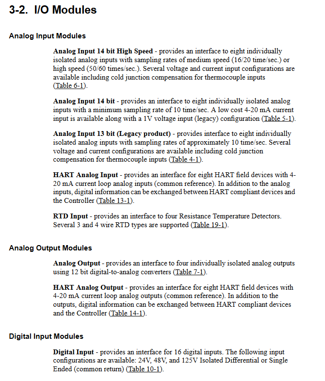
(1) Analog input (AI) module
Module type, number of channels, core specifications, key characteristics
13 bit AI 8 input range: ± 20mV~± 10V, 4-20mA; Resolution of 13 bits; Sampling rate of 10 times/second, supports thermocouple cold end compensation (1C31116G04 module), wire breakage/overcurrent detection
14 bit AI 8 input range: 4-20mA, ± 1V; resolution 14 bits; Sampling rate 20-25 times/second self calibration function, compatible with CE certification
High speed AI 8 input range: ± 20mV~± 10V, 4-20mA; Resolution of 14 bits; Sampling rate of 50-60 times/second, supports high-frequency signal acquisition, suitable for fast response scenarios
HART AI 8 input range: 4-20mA; resolution 16 bits; Sampling rate of 24ms per channel combined with HART digital communication, compatible with smart transmitters, supporting multi parameter acquisition
(2) Analog output (AO) module
Module type, number of channels, core specifications, key characteristics
Standard AO 4 output range: 0-5V/0-10V/4-20mA; Resolution of 12 bits; Update time 2ms overcurrent detection, supports redundant output configuration
HART AO 8 output range: 4-20mA; resolution 16 bits; Load 700 Ω (20mA) digital communication+analog output, supports remote device configuration
(3) Digital Input (DI) Module
Module type, number of channels, core specifications, key characteristics
Standard DI 16 input voltage: 24/48/125VAC/DC; Response time 1.9-40ms, single ended/differential optional, fuse detection (single ended type)
Compact DI 16 input voltage: 24/48/125VAC/DC; Response time ≤ 25ms without Personality module, simplified design, supports separate circuit breaker
Event sequence (SOE) 16 input voltage: 24/48/125VDC; Timestamp accuracy of 125 μ s anti jitter (3ms reject/7ms confirm), event tagging and filtering
(4) Digital Output (DO) Module
Module type, number of channels, core specifications, key characteristics
Standard DO 16 output voltage: 0-60VDC; Output current: 500mA/channel. Communication timeout can be maintained or reset, with fuse detection
Relay Expansion 16 Supports Solid State/Electromagnetic Relay Panel (G2R/KUEP Type) Switching High Voltage/High Current Load (Maximum) 10A@250VAC )
(5) Special function module
RTD module: 4-channel, supports Pt100/Pt200/Ni120/Cu10, 3/4 wire system, accuracy ± 0.2~± 3.5 ℃.
Pulse accumulator module: 2-channel, frequency range 0.1Hz~50kHz, 32-bit counter, supports frequency/pulse counting.
Servo drive module: Suitable for hydraulic servo actuators, supports PI position control, calibration mode (Start/Normal/Local Manual).
Valve locator module: controls speed control valve/globe valve, supports LVDT feedback, redundant configuration, local operation panel (SLIM).
Configuration and wiring specifications
(1) Address Mapping Rules
Module address space: 16 bytes (0~F Hex), core register function:
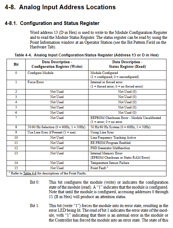
Address 13 (D Hex): Configuration/Status Register (Module Enable, Force Error, Timeout Setting).
Address 12 (C Hex): Point quality register (channel fault, overcurrent/disconnection status).
Address 15 (F Hex): Electronic ID register (module model, serial number).
Channel address allocation: Analog modules occupy consecutive addresses in channel order, while digital modules occupy 1 bit/byte per channel.
(2) Key wiring requirements
Analog signal:
4-20mA signal: Recommended shielded twisted pair cable, with a maximum length of 1000 feet (50pF/ft cable).
Thermocouple: using corresponding types of compensating wires, single point grounding of shielding layer, and temperature sensor installation required for cold end compensation module.
Digital signal:
Single ended input: shared common return line, cable resistance ≤ 100 Ω.
Differential input: Dual wire balanced transmission with stronger anti-interference ability.
CE certification system: All on-site wiring must be braided and shielded, grounded at the cabinet entrance, and unmarked terminals are prohibited.
(3) Power connection
Local power supply: Take power from the Ovation cabinet auxiliary power supply, 24VDC ± 10%, and synchronize CNC power on/off.
External power supply: It must comply with noise standards. Before wiring, disconnect the main power supply to avoid polarity reversal (damaging the module).
Diagnosis and maintenance
(1) Fault diagnosis function
Fault type detection method, alarm indication
Power failure voltage monitoring E LED lights up, status register Bit8 is set to 1
The CH LED for overcurrent/overvoltage current/voltage sampling is on, and the point quality register corresponds to position 1
The fuse fault current monitoring E LED is on, and the status register Bit7 is set to 1
Ground fault impedance detection (<5k Ω) E LED lights up, status register Bit10 is set to 1
Communication failure watchdog timeout: C LED off, I LED on
(2) Maintenance points
Replacement of vulnerable parts:
Fuses: Electronic module (5 × 20mm, 0.5A/250V), Personality module (0.063A~3.15A), need to be replaced with the same specifications.
Battery: Absolute pulse encoder battery (needs to be replaced with power to avoid data loss).
Calibration and configuration:
Self calibration: The simulation module supports controller triggered self calibration to compensate for temperature drift.
Cold end compensation: The thermocouple module needs to be configured with compensation coefficients (B/E/J/K/R/S/T type).
Preventive maintenance:
Regular cleaning: Heat sinks, terminal blocks, avoid chip/oil mist accumulation.
Insulation testing: measured with a 500VDC insulation meter, ≥ 1M Ω qualified.
Deployment mode
Local I/O: Installed in the controller cabinet, communicating through PCI interface cards (PCQL/PCRL), supporting up to 128 modules.
Remote I/O: deployed over long distances via fiber/cable, supporting up to 1024 modules, requiring the configuration of MAU (Media Connection Unit) and RNC (Remote Node Controller).