Emerson Micro Motion High Precision HPC010/HPC015 Series
Installation preparation and environmental requirements
(1) Pre installation checklist
Installation in hazardous areas: Confirm that the certification label level matches the environment;
Temperature compliance: The process medium and ambient temperature are within the equipment limit range;
Flow direction alignment: The flow direction arrow on the sensor housing is consistent with the actual fluid flow direction;
Component matching: Extended core processors correspond one-to-one with sensors.
(2) Key environmental parameters
Restriction type HPC010 HPC015 Remarks
Process medium temperature -50 ℃~125 ℃~46 ℃~200 ℃ Hazardous area certification may have stricter restrictions
Environmental temperature -40 ℃~60 ℃ -40 ℃~60 ℃ Electronic components need to be installed separately if they exceed the range
Vibration limit 5-1000Hz, ≤ 0.35g RMS 5-2000Hz, ≤ 1.0g. When exceeding the limit, anti vibration clamps need to be installed
(3) Best practices for installation
Straight pipe section: No upstream/downstream straight pipe section is required, it can be installed directly;
Pipeline installation:
Vertical pipeline: Liquid/slurry flows upward from bottom to top, gas flows downward;
Block valve: installed downstream of the sensor to avoid fluid backflow affecting the measurement;
Load control: Avoid transmitting bending/twisting loads of pipelines to sensors, without relying on sensors to adjust pipeline alignment;
Support requirement: The sensor does not require external support, and the flange provides all-round support.
Core installation operation
(1) Sensor installation
HPC010 sensor: Use the sensor’s built-in slot for installation. Do not lift it with electronic components or rupture discs to avoid damaging the equipment;
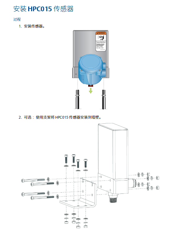
HPC015 sensor:
Basic installation: Directly fix process joints to minimize torque and bending loads;
Optional installation: Wall mounted through brackets or installed with 2 U-bolt pipes.
(2) Installation of electronic components
Enhanced Core Processor:
Direction adjustment: Loosen the 4 fixing screws, rotate the bracket to the desired direction, and tighten the torque to 3-4Nm;
Fixed method: Instrument column/wall installation, pipeline installation requires self provided U-bolts.
MVD Direct Connect intrinsic safety barrier:
Installation: Buckled onto a 35mm DIN rail, with the bottom locking device removed;
Fixed: The end clamping device is tightly attached to the safety barrier and fixed by tightening the screws.
(3) Extended electronic component connection
Cleaning requirements: Keep the extension tube and through tube clean and dry to avoid moisture/impurities damaging electronic components;
Connection steps:
Remove the plastic cap/plug and keep the O-ring on the through tube;
Align the extension tube with the through tube slot, and close the clamp after inserting it;
Tighten the clamp screw to a torque of 1.47-2.03Nm.
Wiring configuration specifications
(1) Classification of wiring options
Reference document for wiring requirements of electronic component options
Integrated transmitter sensor and transmitter pre connected, wiring free transmitter installation manual
Extended electronic components with physical and electrical connections, no additional wiring required. Section 3.5 of this manual
MVD Direct Connect without transmitter, sensor directly connected to host, high-precision MVD Direct Connect instrument manual
The split core processor+transmitter core processor is pre connected to the sensor and requires a 4-wire cable to connect the transmitter. Section 4.2 of this manual
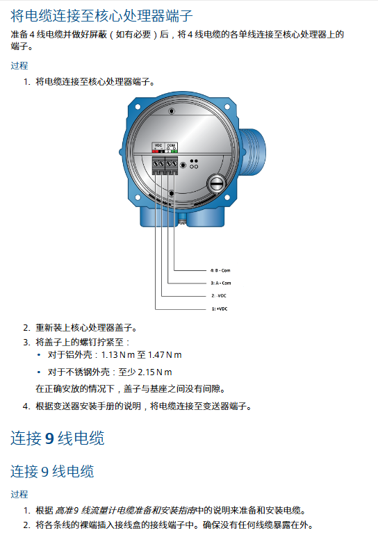
(2) 4-wire cable wiring
cable specifications
Gaozhun provides: shielded/armored type, including power supply (red/black, 0.823mm ²), RS-485 (white/green, 0.326mm ²);
User provided: Twisted pair structure, in compliance with hazardous area requirements, with wire diameter and length matching as follows:
Wiring Function Wire Diameter (mm ²) Maximum Length (m)
Power supply (VDC) 0.326 91
Power supply (VDC) 0.518 152
Power supply (VDC) 0.823 305
Signal (RS-485) ≥ 0.326 305
Wiring steps:
Peel off the sheath (NPT connector 114mm, M20 connector 108mm);
Shielding layer treatment (NPT over 19mm, M20 over 13mm), wrapped with shielding wire for fixation;
Terminal connections: 1 (+VDC), 2 (- VDC), 3 (A-Com), 4 (B-Com);
Cover fixation: Aluminum shell 1.13-1.47Nm, stainless steel shell ≥ 2.15Nm.
(3) 9-wire cable and safety barrier wiring
9-wire cable: wire according to color matching, fully insert the bare end into the terminal, no exposed cables, tighten and fix, and seal the shell;
MVD safety barrier wiring:
Intrinsic safety terminals (connected to core processor): 41 (- VDC), 42 (+VDC), 43 (RS-485 A), 44 (RS-485 B);
Non intrinsic safety terminals (connected to host/power supply): 11 (- VDC), 12 (+VDC), 13 (RS-485 A), 14 (RS-485 B);
Attention: The safety barrier shielding wire should not be connected properly. Multiple devices can share the same power supply (ensure sufficient power supply).
Key points of safety and maintenance
(1) Grounding specifications
Following standards: European IEC 60079-14 (Section 16.2.2.3/4), US Canada ISA 12.06.01;
Technical Requirements:
Wire: copper wire, wire diameter ≥ 2.08mm ²;
Impedance:<1 Ω, with wires as short as possible;
Connection: If the pipeline joint is grounded, the sensor will automatically ground. Otherwise, connect the grounding screw of the electronic component.
(2) Sensor shell blowing
Applicable scenario: After removing the plug of the blowing joint, it is necessary to blow it again;
Preparation items: PTFE raw material tape, argon/nitrogen gas;
Operation steps:
Stop the process or switch to manual control to avoid measurement errors;
Remove the blowing joint plug (away from the bursting disc pressure relief area);
Wrap the plug with 2-3 circles of raw material tape, and connect the air source to the inlet;
Blow gas flow direction: heavy gas flows from bottom to top, light gas flows from top to bottom;
Purging parameters: pressure ≤ 0.5bar, until air is completely replaced;
Sealing: Immediately seal the inlet/outlet with a plug after cutting off the gas source to avoid pressurization.
(3) Pressure relief protection
Explosive disc function: When the flow tube ruptures, release the process medium, and some users can connect the discharge pipeline;
Safety requirements:
Installation direction: Ensure that personnel/equipment are kept away from the pressure relief area to avoid injury from high-pressure fluid jets;
Maintenance: The bursting disc must always be installed and the flow meter should be stopped after damage;
Protection level: After modifying the blowing joint/blind plug/bursting disc, the IP66/IP67 level must be maintained.