Eaton MP-3000 series motor protection relay
Core technical parameters
Category specific specifications
Electrical input CT input: 5A or 1A; Control power supply: 120/240VAC (± 10%/-25%), power consumption ≤ 24VA; Discrete input: 2 channels (120VAC)
Electrical output relay output: 4-channel Form C( 5A@120 /240VAC、 5A@30VDC ); Analog output: 4-20mA (accuracy ± 1%)
Measurement accuracy of phase current: ± 1% (1A-10I ₙ); Grounding current: ± 1.5% (below 55% I ₙ), ± 2% (above 55% I ₙ)
Protection setting range overload current: 10-3000A; grounding fault: 2-55% CT rated current; Locked rotor current: 100-1200% FLA
Environmental characteristics: Operating temperature: -20 ° C~+60 ° C; Storage temperature: -45 ° C~+85 ° C; Impact resistance: 30g; Vibration resistance: 5g
Mechanical characteristics fixed size: 260.4 × 170 × 109mm (H × W × D); Weight: 1.8kg (excluding accessories)
Detailed explanation of core functions
Protection function (including ANSI device number)
|Function Name | ANSI Number | Core Parameters and Description|
|I ² t overload protection | 49/51 | Based on motor nameplate data adaptive curve, supports RTD temperature compensation, and can monitor thermal accumulation degree (0-100%)|
|Blocked rotor protection | 49S/51 | Set range 100-1200% FLA, startup delay 0-1200 seconds, running delay 0-240 seconds|
|Instantaneous overcurrent protection | 50 | Setting range 300-1600% FLA, startup delay 2-60 cycles, no operating delay, suitable for fast tripping in short circuit faults|
|Grounding fault protection | 50G | Setting range 2-55% rated current of grounding CT, startup delay 2-60 cycles, operation delay 0-60 cycles, supports zero sequence CT input|
|Phase imbalance/phase sequence reversal protection | 46 | Unbalance setting 4-40%, phase sequence error immediately trips, start-up delay 0-120 seconds, operation delay 0-240 seconds|
|Underload protection | 37 | Set range 6-90% FLA, startup delay 0-120 seconds, running delay 0-240 seconds, adapted to load loss fault|
|RTD temperature protection | 49/38 | Supports winding/bearing temperature monitoring, trip setting 0-199 ° C, alarm setting 0-199 ° C, requires URTD module|
|Start frequency limit protection | 66 | Set 1-10 times/time window (1-240 minutes), support 1-5 cold start continuous operation|
Control and monitoring functions
Startup Control: Supports cold start frequency limit, startup interval control (1-240 minutes), anti reverse delay (1-3600 seconds), and long acceleration time setting (1-200 seconds)
Load control: Load unloading function (AUX1 relay specific), can set pickup/dropout current (50-150% FLA) and delay (0-5 seconds)
Monitoring data: three-phase current, ground current, phase imbalance, RTD temperature (11 channels), heat accumulation degree (% I ² t), operating time, start-up curve (last 4 times)
Recording function: 100 event logs, 20 trip/alarm records, motor operation statistics (starting times, longest operating current, etc.)
Programming and Configuration
Programming method
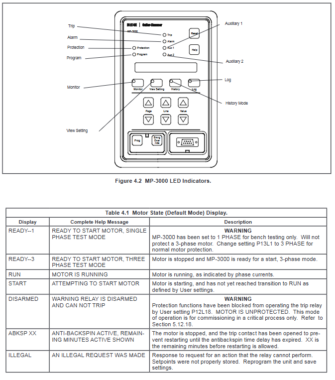
Front panel programming: Operated through 6 navigation keys and 10 LED indicator lights, supporting 6 modes (default/monitoring/viewing/programming/history/log)
Software programming: PowerNet (multi device networking), PowerPort (single device direct connection), supports parameter download/upload, and startup curve viewing
Communication programming: requires PONI module, supports INCOM/Modbus/DeviceNet/Ethernet protocol, RS-232 interface (temporary programming)
Key programming pages
|Page Number | Page Name | Core Configuration Item|
|Page 1 | SP MOTOR | Motor nameplate parameters (FLA/LRC/LRT/UTC), CT ratio (PCT/GCT), power frequency (50/60Hz)|
|Page 2 | SP RTD | RTD temperature units, trip/alarm thresholds, diagnostic switches|
|Page 3 | SP TRIP | Trip thresholds and startup/operation delays for various protection functions|
|Page 4 | SP ALARM | Various alarm thresholds and operational delays|
|Page 5 | SP START | Start control parameters (frequency/interval/cold start/transition current/anti reverse) | | Page 8-10 | SP AREL/AUX1/AUX2 | Alarm/AUX1/AUX2 relay trigger condition configuration (supports 22 event selections)|
|Page 12 | SP SYS | System configuration (output mode, I ² t reset mode, emergency override enable, clock settings)|
|Page 13 | SP TEST | Input/Output Test (Relay Forced Action, Analog Output Forced Value)|
Installation and wiring
Installation requirements
Installation method: Panel installation, standard IQ cutout size (136.65 × 68.33mm), fixed type requires 35mm DIN rail or screw fixation
Pull out feature: Supports hot swapping, CT circuit self short circuit design, URTD module requires remote installation (fiber optic up to 120m)
Environmental requirements: Keep away from high temperatures and vibration sources, with a ventilation gap of ≥ 50mm, and the grounding terminal must be reliably grounded (# 14 AWG or above cable)
Key Wiring Specification | Wiring Type | Wiring Requirements|
|CT wiring | The secondary side of the three-phase CT is connected to H1A-H2A/H1B-H2B/H1C-H2C, the grounding CT is connected to G1, the single end is grounded, and the cable needs to be shielded|
|Power wiring | Control power supply terminals 4 (L) and 7 (N), 120/240VAC automatic adaptation, requiring independent fuse protection|
|Discrete input wiring | 2-channel discrete input (terminals 8/10), common terminal connected to terminal 9, requires 120VAC power supply (provided by terminal 6)|
|Output relay wiring | Trip relay (terminals 11-13) in series with contactor coil, alarm/AUX 1/AUX 2 configured control circuit as needed|
|URTD wiring | Supports fiber optic (recommended) or 3-wire cables, with a maximum fiber optic length of 120m and a maximum cable length of 152m, shielded layer single ended grounding|
Maintenance and troubleshooting
routine maintenance
Regular inspection: Check the panel indicator lights and operating parameters monthly, and verify the CT wiring and grounding status annually
Cleaning requirements: Wipe the panel with a soft damp cloth, avoid corrosive cleaning agents, and prevent liquids from entering the equipment
Calibration cycle: It is recommended to calibrate the current measurement accuracy and RTD temperature measurement accuracy every 2 years
Spare parts replacement: URTD module, PONI module, and pull-out internal chassis can be replaced separately
Common faults and solutions | Fault phenomena | Possible causes | Solutions|
|Start and trip (IOC) | Excessive starting current or CT wiring error | Increase IOC setting or extend starting delay, check CT polarity and wiring|
|Thermal overload trip (LRC/I ² t) | Overloading or phase imbalance | Check the motor load and investigate the balance of power supply phase voltage|
|Ground Fault Alarm (GND Fault) | Motor Insulation Decrease or Wiring Leakage | Shutdown and Check Motor Insulation, Investigate Cable Damage|
|RTD has no data (MONT RTD has no display) | URTD module is not communicating or fiber is disconnected | Check the URTD power supply and fiber connection, restart the device|
|Communication failure | PONI module address conflict or protocol mismatch | Reset PONI address and confirm communication protocol configuration|
Accessories and Selection
Core attachments
|Attachment Name | Model Example | Function Description|
|URTD Temperature Module | 2D78559G01 | Supports 11 RTD inputs (copper/nickel/platinum material), requires fiber optic or 3-wire cable connection|
|PONI Communication Module | 66D2028G01 (EPONI) | Ethernet Communication Module, supports PowerNet networking, requires external power supply (optional)|
|Fiber optic cable | MPFO-10 | 10 meter pre cut fiber optic, compatible with URTD module and relay connection, low loss design|
|Installation bracket | 66D2053G01 | PONI module dedicated installation bracket, suitable for fixed relay back installation|
|Pull out housing | MP3X11-OC | Pull out relay external chassis, supports CT self short circuit, compatible with fixed internal chassis upgrade|
Key selection points
Current level: Select 5A or 1A CT input model based on motor FLA
Communication requirements: Select INCOM/Modbus/DeviceNet/Ethernet PONI modules as needed
Temperature monitoring: When RTD temperature protection is required, URTD module and fiber/cable should be selected as an option
Installation scenario: Choose the pull-out type for harsh environments or frequent maintenance, and the fixed type for regular scenarios