DEIF MULTI-LINE 2 Option X Additional display and operator panel
Detailed explanation of three core options
Option model, core component connection method, expansion quantity limit, key characteristics
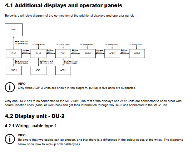
X2 DU-2 additional display unit CAN bus with 3 supports multi bit start stop, alarm confirmation, parameter reading and writing; CAN ID (0-3) and communication protocol need to be configured
X3 AOP-1 additional operation panel serial communication 1/DU-2 16 configurable LEDs+8 configurable buttons; Need to rely on DU-2 power supply and communication, with a maximum distance of 0.5 meters
X4 AOP-2 additional operation panel CAN bus 5 x 16 configurable LEDs+8 configurable buttons; Support lamp inspection/dimming, status relay output; Maximum distance of 200 meters
X2 option (DU-2 display unit)
Function: As a host extension display, it can achieve parameter reading and writing (main display), parameter monitoring (secondary display), and support switching between master and slave displays (password input).
Communication configuration:
CAN ID: 0-3 optional, 0 means CAN communication is turned off, DU-2 connected to the host needs to be set to 1.
Protocol selection: 3 protocols, compatible with different software versions of hosts (Protocol 3 supports the latest version of hosts).
Terminal resistance: The CAN bus head and tail devices need to turn on a 120 Ω resistor (Dip switch 1 set to ON).
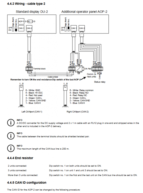
Wiring: Supports 2 types of cables, requires shielded twisted pair, away from power cables, with a maximum length of 200 meters.
X3 option (AOP-1 operation panel)
Hardware: 16 status indicator LEDs (1-16), 8 function buttons (1-8), no independent CAN ID (determined by the connected DU-2).
Connection: Connect the AOP-1 interface of DU-2 through a dedicated cable, while obtaining power and communication, with a maximum distance of 0.5 meters.
Programming: You need to download the PC utility software from the DEIF official website to configure the LED and button functions.
X4 option (AOP-2 operation panel)
Hardware: 16 LEDs+8 buttons, including independent status relays (activated 5 seconds after power on), supporting light detection/dimming functions (short press light detection, long press dimming).
Communication configuration:
CAN ID: 0-5 optional, default 1, adjust by button 7/8, save by button 6.
Terminal resistor: Same as X2 option, the first and last devices are equipped with 120 Ω resistors.
Wiring: Shielded twisted pair cable, 2 cable types to choose from, maximum communication distance of 200 meters, including DC/DC converter and dedicated cable.
Key configurations and operations
CAN ID configuration rules
|Option type | CAN ID range | Special requirements|
|DU-2 | 0-3 | The DU-2 connected to the host must be set to 1; 0 means CAN communication is turned off|
|AOP-2 | 0-5 | Default 1; 0 means CAN communication is turned off|
|AOP-1 | – | No independent ID, following the connected DU-2|
Terminal resistance setting
Two devices connected in series: Dip switch 1 on both ends of the device is set to ON.
Three devices are connected in series: Dip switch 1 for the head and tail devices is set to ON, and the middle device is set to OFF.
More than 3 devices: Only the terminal resistors of the CAN bus head and tail devices are turned on.
Master slave display function (DU-2 only)
|Configuration scenario | Main DU-2 function | Slave DU-2 function | Corresponding CAN ID setting|
|Only 1 DU-2 connected to host | read-write | – | DU-2 connected to host is set to 0|
|1 Master 1 Slave DU-2 | Read/Write | Read Only | DU-2 connected to the host is set to 1, and the slave is set to 2|
|1 master multiple slave DU-2 (up to 2 slaves) | Read/Write | Read Only | Set the DU-2 connected to the host to 1 and the slave to 2/3|
Master slave switching: Long press the “View” button for 3 seconds from DU-2, enter the customer password to switch to the main display, and the original host will automatically change to the slave display.
Error Handling and Programming
Common error: CAN ID conflict
Alarm prompt: DU-2 displays “Warning: Two displays have the same CAN ID Press Enter”.
Solution: Press Enter to enter the CAN ID modification menu and select an unoccupied ID.
Programming support
Applicable objects: LED and button function configuration for AOP-1 and AOP-2.
Tool: PC utility software (available for download from the DEIF official website).
Guidance: Refer to the built-in Help function of the software to obtain programming steps.