DEIF LSU-112DG Load Distribution Unit
Basic Product Information
LSU-112DG is a generator load distribution unit developed by DEIF, with ANSI code 90. Its core is used for prime mover control of diesel and gas generators, achieving frequency and power control of generators and precise load distribution when multiple generators are connected in parallel. The product is installed on a 35mm DIN rail or base, equipped with LED status indicator lights (displaying device operating status and activated control functions), built-in microcontroller for core logic control, and self-monitoring function. The overall design is suitable for industrial, maritime and other generator control scenarios, document number 4921240118I.
Core Application Mode and Governor Adaptation
Three operating modes
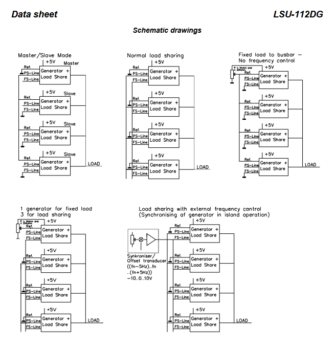
LSU-112DG can achieve three types of precise control according to the operating scenario of the generator, covering the entire scenario from single machine to multi machine parallel connection:
Single machine mode: Independently control the generator, execute frequency control, and maintain stable output frequency of the generator;
Grid connected mode: The generator is connected in parallel with the power grid, and power control is performed to stabilize the output power according to the set value;
Multi machine parallel mode: operates in parallel with other generators, while performing frequency and power control to achieve reasonable load distribution among multiple units.
Governor adaptation
Native support for direct connection of mechanical speed controllers;
Paired with DEIFEPN-110DN or EPQ-96 electronic potentiometers, it can be extended to support electronic speed controllers and adapt to different types of generator speed control systems.
Core Measurement and Sensing Functions
Built in sensors
Built in frequency sensor: enables precise measurement of generator frequency. If higher frequency stability is required, an external common external frequency sensor can be connected (applicable to all LSU-112DG in the power station);
Built in power sensor: designed based on the I × cos φ principle, supports two types of wiring coupling methods, with 1W3 (three-phase three wire, balanced load) as the standard configuration and 1W (4) as single-phase coupling, meeting the measurement needs of different power supply systems.
Expansion of External Sensors
Power sensor: When there is an unbalanced load on the generator, an external power sensor with a 4-20mA DC output can be connected (recommended DEIF TAS-331DG). At this time, the built-in power sensor will automatically disconnect and the external sensor will take over the measurement;
Frequency sensor: When multiple generators are synchronized to the bus at the same time, an external frequency sensor can be connected to control the frequency uniformly and improve synchronization accuracy.
Core Control and Protection Functions
Proportional load distribution (core function)
LSU-112DG needs to be calibrated according to the actual capacity of the corresponding generator to achieve proportional load distribution when different capacity units are connected in parallel. For example, if a 100kW+150kW unit is connected in parallel, the total load of 125kW will be divided into 50kW and 75kW according to a 4:6 ratio;
Equipped with a positive Derating potentiometer, the large unit can be operated at a reduced capacity (with an adjustment range of 50~0% P ₙ). After the reduction, the load of the unit will be evenly distributed according to the reduced capacity. For example, if a 150kW unit is reduced to 100kW, it will share a load of 125kW (62.5kW each) with the original 100kW unit.
Speed Control Output
The unit is equipped with 2 relay contact outputs (speed up SG/speed down SG) for controlling the servo motor of the prime mover. The speed control logic is implemented by the built-in P controller, and the control accuracy is adjusted through three core parameters. The parameters can be set as needed:
TN (minimum on-time): The minimum duration of control pulses within the proportional band, ranging from 25 to 500ms;
XP (Proportional Band): The interval in which the pulse/pause ratio varies proportionally with frequency/power deviation, ranging from 0 to ± 50% P ₙ or 0 to ± 2.5Hz set frequency;
TP (cycle time): The interval time between two consecutive relay pulses, default 10 × TN, can be set to 5 × TN/15 × TN/20 × TN through jumper wires.
Simultaneously set dead zone: the deviation interval without control pulse output, the power dead zone defaults to * * ± 2% P ₙ * * (jumper can be set to ± 4%), and the frequency dead zone defaults to * * ± 0.1Hz * * (jumper can be set to ± 0.25Hz).
Unloading function
Equipped with a potential free unloading input (33/34 terminals), two core actions are achieved after activation:
Adjust the generator power to zero power;
Disconnect the power output and power parallel line (PS) of LSU-112DG to avoid interference with other parallel units.
Automatic protection and disconnection
When the following situations occur, the built-in relay will automatically disconnect the power/frequency output of the unit from the parallel line (PS/FS) to ensure system stability:
The L1/L2 phase of LSU-112DG is disconnected, and the corresponding generator is disconnected from the busbar;
The auxiliary power supply voltage of LSU-112DG is disconnected;
When the unloading input is activated (only disconnect the power parallel line PS).
Self monitoring function
Built in microcontroller program running status self-monitoring, feedback through green POWER LED light and 17/18 status output terminal:
Green light constantly on: power supply is normal, unit operation is correct, 17/18 terminals are closed;
Green light flashing at 2-3Hz: power supply is normal, unit operation is faulty, 17/18 terminals are disconnected (activated fault state).
Key Terminals and Signal Output
The LSU-112DG is equipped with multiple sets of functional terminals, covering all requirements such as power supply, measurement, control, parallel connection, and expansion. The core terminal functions are shown in the table below (key terminals):
Terminal number identification/name, core function, key parameters/description
1/3 X1/X2 power supply voltage input AC 57.7~690V/DC 24~110V, UL only supports 24V DC/110V AC
17/18 Sta (status) status output closed normally, fault disconnected
28/29 IL1 current measurement input external current transformer S1 → 28, S2 → 29
31/32 Ext. P. (External Power) External power sensor input 4-20mA DC, built-in sensor needs to be short circuited when in use
33/34 Unl (Unloading) Unloading input connected to a potential free normally open relay contact, activated to zero power
35/36 Ref./⊥ (reference/ground) power reference input 0.5~5V corresponds to 10~100% power, 0.55V activated/0.45V deactivated
37/36+5V/⊥ reference voltage output 5.0V ± 1%, maximum load 5mA, used for local power control
38/39 FS/⊥ frequency parallel line -5~+5V analog quantity, 0V=0Hz, 5V=2.5Hz
40/41 PS/⊥ power parallel line -5~+5V analog quantity, 5V=100% power (when cos φ=0.8, 4V=100%)
43/44, 45/46 SG (speed up/down) speed control relay outputs AC1/DC1: 250V/24V 8A; AC15/DC13:250V/24V 3A
Note: All terminals marked with ⊥ are interconnected internally; When connecting a DC servo motor, the SG relay needs to be externally connected to an auxiliary relay, and transient suppressors should be connected at both ends of the relay coil.
Technical Specifications (Key Parameters)
Measurement specifications
Measurement parameter range/specification, overload capacity, load requirements
Measure current (I ₙ) 0.3~1.5A AC (calibration module), UL version 0.4~5.0A AC 20 × I ₙ for 10 seconds (maximum 75A); Maximum 0.5VA per phase at rated current of 80 × I ₙ for 1 second (maximum 300A)
Measure voltage (U ₙ) 57.7~690V AC, UL version 57.7~450V AC 1.2 × U ₙ Continuous operation 2k Ω/V
Electrical output specifications
Key Explanation of Output Type Range/Accuracy
PS/FS parallel line -5~+5V, 5V ± 2%=2.5Hz/100% power dual analog parallel line, realizing multi machine data exchange
Reference voltage output 5.0V ± 1% maximum load 5mA (R ≥ 1k Ω), UL version ± 5V DC
Optocoupler output maximum 30V DC/5mA, voltage drop 1.5V@2mA Output shutdown in case of system failure, UL version 30V DC/5mA
Speed control relay output AC1/DC1:8A; AC15/DC13:3A UL version only supports resistive loads
Environmental and Physical Specifications
Project Specification UL/cUL Version Special Requirements
Working temperature -25~70 ℃ (-13~158 ℉), maximum ambient temperature 60 ℃ (140 ℉)
Temperature drift setting value maximum ± 0.2% full-scale/10 ℃ same as left
Electrical isolation measurement/relay/analog IO/auxiliary power supply room 3250V AC 50Hz 1min same as left
Protection level: enclosure IP40, terminal IP20 (IEC/EN 60529) same as left
All plastic parts are made of UL94-V1 self extinguishing material, the same as the left
Weight approximately 0.750kg on the left
Wiring specifications: single strand maximum 4.0mm ², multi strand maximum 2.5mm ²; AWG 12-16 copper wire only uses 60/75 ℃ copper conductor
Other certifications and standards
EMC: Compliant with IEC/EN 61000-6-1/2/3/4;
Climate grade: DIN 40040 HSE grade;
Classification Society Certification: Uni line series components have been recognized by mainstream maritime classification societies, and the latest certification can be found on the DEIF official website;
UL certification: Provided on demand. If the product is re customized outside the DEIF Denmark factory, it will lose UL certification.
Adjustable Parameters and LED Indication
Core Adjustable Parameters (Range)
The control parameters of LSU-112DG can be adjusted as needed, and the core parameter adjustment range is shown in the table below. The jumper can expand the parameter range of some parts:
Parameter Name Adjustment Range Remarks
TN (Minimum Connection Time) 25~500ms Basic Speed Control Parameters
XP (proportional band) 0~± 50% P ₙ/0~± 2.5Hz Set frequency, choose one, configure according to control requirements
Set the frequency to 45-65Hz to cover the mainstream generator frequency standard
Derating 50~0% P ₙ adjusted according to the unit’s derating requirements
TP (cycle time) 10 × TN (jumper can be set to 5/15/20 × TN) and TN linkage
Power dead zone ± 2% P ₙ (jumper can be set to ± 4%) After derating, calculate according to the derating value
Frequency dead zone ± 0.1Hz (jumper can be set to ± 0.25Hz) to reduce ineffective speed regulation pulses
LED Status Indication
Equipped with multi-color LED lights, providing intuitive feedback on the operation status of the equipment and generator. If there are no additional indicator lights, it means that the corresponding function is not activated:
LED identification function is constantly on (status) and off (status)
UG (green) generator voltage is normal, but there is a voltage fault
Unload (green) The generator unloading unit has been unloaded (zero power) and is operating at normal load
SG (yellow) speed up/down control corresponding to speed up/down relay activation relay not activated
Note: After the equipment installation and calibration are completed, the transparent front cover can be sealed to prevent parameters from being mistakenly modified.