EATON MP-3000 Advanced Motor Protection Relay
Product basic positioning and core advantages
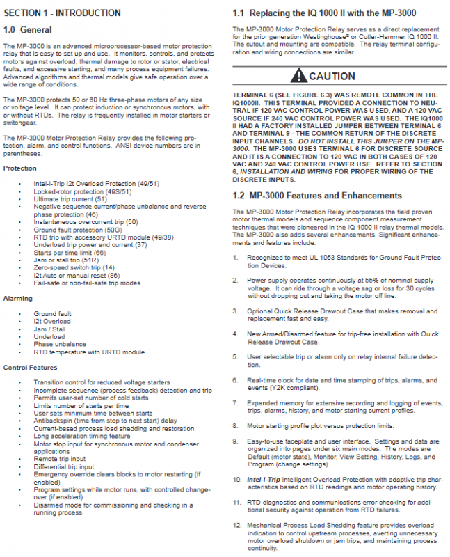
Core positioning: A multifunctional motor protection relay based on microprocessors, suitable for three-phase induction/synchronous motors in medium and low voltage distribution systems. It can integrate protection, monitoring, control, and metering functions and is widely used in industrial equipment such as pumps, fans, and conveyors;
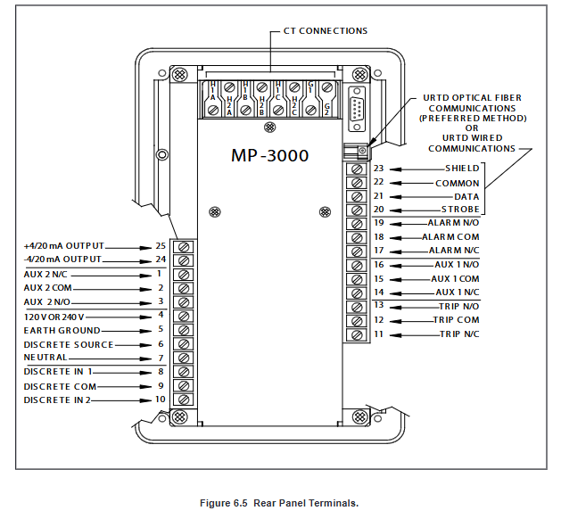
Alternative features: Compatible with IQ 1000 II installation openings, similar terminal configuration, can be directly retrofitted for replacement, only need to pay attention to the functional change of terminal 6 (original REMOTE COMMON changed to DISCRITE SOURCE);
Core strengths
Comprehensive functionality: covering 10+motor protection scenarios, supporting RTD temperature expansion and multi protocol communication;
High reliability: voltage drop withstand 13 cycles of 60Hz, anti-interference up to IEC 61000-4 series standards;
Flexible adaptation: Supports fixed/drawer installation, 1A/5A CT optional, compatible with multiple communication protocols;
Strong usability: The front panel provides intuitive operation, supports remote programming and data export, and log recording facilitates fault tracing.
Core hardware and technical parameters
(1) Key electrical parameters
Category specific parameters
Power configuration rated at 120/240VAC, allowable fluctuation range 19.2-30V; frequency 47-63Hz (compatible with 50/60Hz)
Current measurement accuracy: phase current ± 1% (0~In), ground current ± 1.5% (0~55% In); CT ratio 10-4000:1
Discrete input 2-channel programmable, 120VAC excitation, isolation voltage 1500VDC
Output contact 4-channel Form C, instantaneous on-off 30A (0.25 seconds), continuous on-off 5A (120/240VAC)
Analog output 4-20mA, accuracy ± 1%, load ≤ 1k Ω
Communication capability baud rate 1200-38400bps, INCOM protocol maximum transmission 10000 feet
(2) Expansion module specifications
URTD module: supports 11 RTD inputs (10 Ω copper/100 Ω nickel/120 Ω nickel/100 Ω platinum), can monitor winding and bearing temperatures, and communication supports fiber optic (up to 121.9m) or 3-wire cable (up to 152m);
PONI communication module: Provides INCOM/Modbus/DeviceNet/Ethernet interfaces, supports remote programming, data reading, and trip control.
Detailed explanation of core functions
(1) Protection function system
Thermal overload protection (I ² T algorithm)
Generate exclusive protection curves based on motor nameplate parameters (FLA/LRC/LRT), supporting adaptive RTD temperature feedback;
Effective current calculation: I2=I2+kI2 (where k is the negative sequence current weighting coefficient), taking into account the influence of 5th, 7th, 11th, and 13th harmonics;
Trip threshold: Maximum trip current (UTC) 85-150% FLA (usually set as service factor x 100%).
Key protection function parameters
|Protection type | Setting range | Core function|
|Grounding fault | 2-55% grounding CT ratio, OFF optional | Detecting winding to ground insulation fault, supporting startup/operation delay (2-60 cycles)|
|Instantaneous overcurrent | 300-1600% FLA, OFF optional | Quickly cut off short circuit faults, start delay 2-60 cycles to avoid closing shock|
|Locked rotor protection | 100-1200% FLA, OFF optional | Monitor motor jamming, start delay 0-1200 seconds, run delay 0-240 seconds|
|Phase imbalance | 4-40% negative/positive sequence ratio, OFF optional | Prevent single-phase operation from burning out, support alarm/trip dual mode|
|Underload protection | 6-90% FLA, OFF optional | Detect load loss (such as coupling failure), delay 0-240 seconds|
(2) Control and monitoring functions
Start control: up to 5 cold starts, 1-10/1-240 minute start limit, 1-240 minute start interval, 1-3600 second anti reverse delay;
Pressure reduction startup switching: supports four switching logics: time/current/time+current/time¤t, switching current 10-300% FLA;
Load unloading: Automatically cut off part of the load when overloaded, unload current 50-150% FLA, restore current lower than unload current, delay 0-5 seconds;
Monitoring data: 3-phase current/line voltage, zero sequence current, power factor, frequency (45-65Hz, accuracy ± 0.02Hz), 2-15th harmonic, RTD temperature (0-199 ℃, ℃/℉ optional).
(3) Logging and recording function
Event log: 100 records, including timestamps (1ms accuracy), recording protection actions, changes in contact status, and modifications to set values;
Trip/alarm log: 20 records, including the reason for the trip, electrical parameters at the time of the fault, and setting group information;
Startup curve: The current time curve of the last 4 startups can be exported to PowerNet software for analysis through the communication interface.
Programming and Operation Guide
(1) Operation mode
Mode core function operation entrance
Default mode displays motor status (READY/RUN/START), alarm/trip information, power on default, press Reset button to exit other modes
Monitoring mode allows real-time viewing of current, temperature, frequency, I ² T percentage, etc. Press the Monitor button
Modify protection parameters, I/O configuration, and communication settings in programming mode. Open the security door and press the Program key (password required)
View trip/alarm frequency, cumulative running time, and startup statistics in historical mode. Press the History button
View event logs and trip details in log mode. Press the Log button
(2) Key programming settings
Motor parameters (P1L1-P1L9): Strictly follow the motor nameplate configuration FLA (10-3000A), LRC (300-1200% FLA), LRT (1-120 seconds), CT ratio (PCT/GCT);
Protection threshold (P3L1-P3L14): Ground fault tripping 24% Ground CT ratio (default), instantaneous overcurrent 1.5 times LRC (recommended), phase imbalance 10% (default);
System configuration (P12L1-P12L18): Output mode (MODE1/MODE2), I ² T reset mode (automatic/manual), emergency override enable/disable, ARMED/ISARMED mode;
Test mode (P13L1-P13L8): Supports 1-phase/3-phase testing, forced action of output relays, and simulated output testing.
Installation and wiring specifications
Installation requirements: Vertically installed on grounded steel panels, with hole sizes in accordance with manual requirements, and a ventilation gap of ≥ 30mm reserved around the perimeter;
Wiring specifications
CT wiring: 3-phase CT adopts star connection, zero sequence CT is recommended for grounding CT (higher sensitivity), and the CT secondary side is single ended grounded;
Power wiring: Terminal 4 (fire), 7 (zero), automatic adaptation to 120VAC and 240VAC, URTD module requires separate 120VAC power supply;
Discrete input: terminals 8 (DI1), 10 (DI2), 9 (common terminal), using 120VAC wet contacts;
Output wiring: Trip relay (terminals 11-13) in series with contactor coil, alarm/auxiliary relay configured as needed;
Grounding requirements: The cross-sectional area of the functional grounding conductor should be ≥ 1.5mm ², the length should be ≤ 350mm, and the tightening torque should be 1.3Nm.
Testing and Maintenance
Pre startup inspection: power supply voltage, CT wiring polarity, motor parameter settings, grounding continuity;
Functional testing:
Output test: On the SP TEST page in Program mode, force tripping/alarm/auxiliary relay action;
Current test: Compare the clamp meter and panel display values during operation (error ≤ 5%);
Communication testing: Read real-time data and export logs through PowerNet software;
Daily maintenance:
Battery inspection: Regularly test the voltage of lithium batteries, with a backup life of 10 years at 25 ℃;
Cleaning: Wipe the panel with a soft cloth and do not use solvents;
Log export: Regularly export event logs to analyze fault trends.
Ordering and accessory information
Product Model Core Configuration Style Number
MP3010 fixed model, 5A CT, no communication 66D2205G01
MP3110MODBUS Fixed, 1A CT, Modbus Communication 66D2205G07
MP3011 drawer style, 5A CT, no communication 66D2207G01
MP3010VPI Fixed, 5A CT, INCOM+URTD+FOC 66D2036G51
Accessory Description Model
URTD module 11 channel RTD input 2D78559G01
10 meter pre cut fiber optic cable 66D2037G03
PONI module Ethernet communication module 66D2028G01
Installation bracket PONI module installation bracket 66D2053G01