Durant Ambassador Series 5760X-405 Counting Controller Operating Instructions
Counting and Rate Core Module
Module Name Key Parameters Function Description
Main counter with 6 bits, bidirectional counting, 4 preset (P1-P4) core counting modules, supports increment/decrement, can set final preset (Pf), supports resetting to zero/preset value, supports automatic cycle counting
Batch counter with 6 digits, increment only, 1 preset records the “batch” quantity of the main counter, the main counter automatically cycles or increments when reaching the final preset, and automatically cycles after reaching the preset
Accumulator 8-bit, bidirectional counting and parallel counting with the main counter. The main counter accumulates in the forward direction and decreases in the reverse direction, without preset or output functions
Rate meter (1/Tau) 5-digit display, 2 alarm setpoints based on the pulse frequency of input A to calculate the rate (such as revolutions per minute, barrels per hour), supports upper and lower limit alarms, not available for foot/inch models
Input/Output and Communication Module
input module
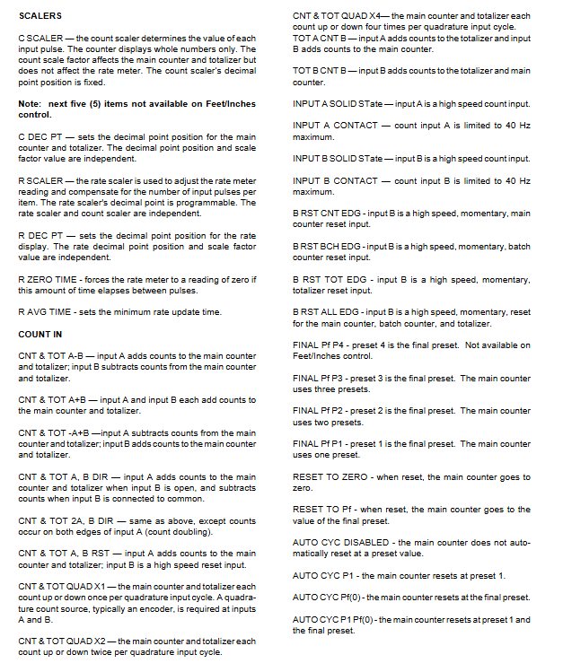
Counting input: A/B dual input, supports current injection/pulling signals (DIP switch selection), compatible with differential signals/single ended DC signals, supports 8 counting modes (such as QUAD X1/X2/X4, A+B increase/decrease, A-B increase/decrease, etc.);
Control inputs: 4 programmable inputs (current only), capable of assigning 14 functions (such as reset, output control, print trigger, program lock, etc.);
Input characteristics: Count input maximum rate of 8000Hz (solid-state signal), control input response time ≥ 15ms.
output module
Relay output (2): SPDT contact, UL rated 250VAC/360VA, supports latch/pulse/follow mode, adjustable delay time (0.00-99.99 seconds);
Solid state output (2): NPN open collector, maximum 30VDC/200mA, with transient protection, suitable for low-power load control;
Output logic: It can be associated with count presets, rate alarms, control input events, and supports forward/reverse modes.
communication module
Interface type: RS-485 (terminal 21-22+RJ-11 modular interface);
Working modes: host mode (responding to commands from the upper computer), printer mode (outputting data after triggering);
Communication parameters: baud rate 300/1200/2400/4800/9600/19200, data format 1 start bit+7 data bits+1 check bit+1 stop bit, supports Odd/Even/None check;
Transmission content: 12 types of data, including counting, rate, preset values, etc., can be selected, and cross project replication is supported.
Special Features (Foot/Inch Control)
Only models 57601-415 (green display) and 57601-465 (red display) are supported, core features:
Display format: 6-digit number, with the first 4 feet and last 2 inches separated by a fixed decimal point;
Count range: 0.00-9999.11 feet inches, overflow to zero (120000 counts), overflow to 119999;
Preset settings: Supports P1-P3+pre alarm (Pw), pre alarm value ≤ final preset (Pf), Pw automatically synchronizes interval when Pf changes;
No speed function: does not support speed meters, speed alarms, and related display screens.
Key Technical Parameters (Summary Table)
Category specific parameters
Power supply specifications: DC version: 10-15VDC, maximum 300mA; AC version: 115/230VAC (± 15%), 50-60Hz, 7W
Environmental parameters Operating temperature: 0-55 ℃ (60Hz)/0-50 ℃ (50Hz); Storage temperature: -20-70 ℃; Relative humidity: 85% RH (no condensation)
Protection level NEMA 4 (requires installation with the provided gasket)
Display feature type: green backlit LCD/reverse red LCD; Specification: 2 x 8 characters, character height 0.30 inches (7.62mm)
Counting input signal type: current filling/pulling (DIP selection), AC signal maximum 17VAC (48V peak to peak); Speed: Solid state signal up to 8000Hz, contact signal up to 40Hz
Control input voltage range: high 3.7-24VDC, low 0.0-0.9VDC; Response time: minimum low level 15ms, minimum high level 15ms
Output parameter relay: SPDT contact, 250VAC/360VA; Solid state: NPN open collector, 30VDC/ 200mA@1.3VDC
Physical dimensions of the casing: 67mm (W) × 67mm (H) × 142mm (D); Panel opening: 68mm (W) × 68mm (H); Weight: 0.54kg
Wire specification 14-22AWG (2.1-0.38mm ²), 600V, supports single/multiple/fuse wire
Installation and wiring specifications
Installation requirements
Installation method: panel installation, equipped with 1 gasket, 2 installation buckles, and 4 screws;
Gasket installation: The gasket has adhesive on one side and needs to be positioned and pasted once to avoid repeated tearing and pasting, which may cause sealing failure;
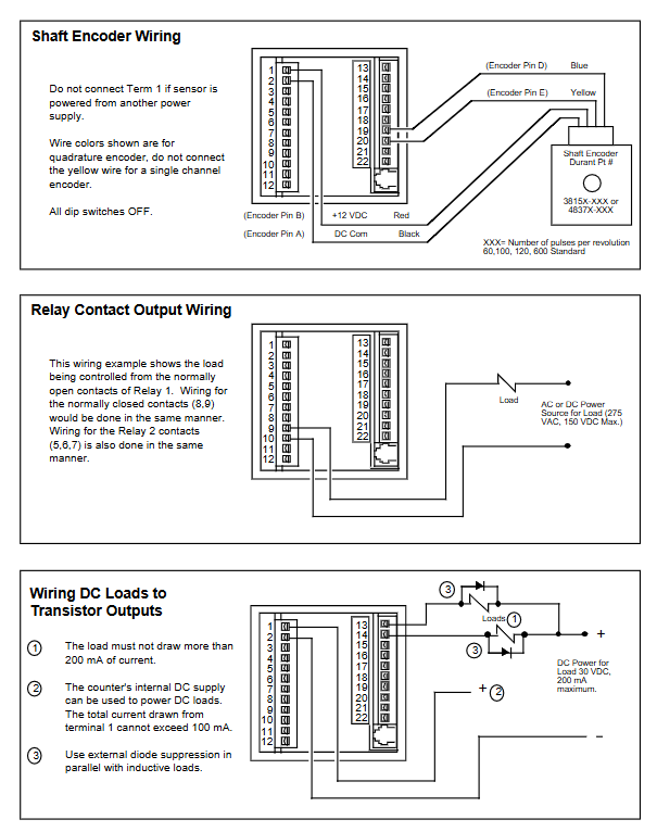
Wiring principle: Disconnect all power sources before wiring; Shielded wires are used for signal cables, and the shielding layer is connected to the common terminal of the counter (terminals 2-4); Separate the wiring of power and signal lines into slots to avoid bundling;
Power requirements: Use a “clean” power supply, avoid sharing power with the load, and add a power filter if it seriously interferes with the environment.
Terminal configuration (core terminal)
| Terminal number | Function | Key description |
| 1 | Power input/output | DC model: 10-15VDC positive pole; AC model: 12VDC output (± 25%, 100mA max) | | 2-4 | DC common terminal | Counting/control input reference ground, transistor output current sink terminal |
| 5-7 | Relays 2 | 5 (NC), 6 (COM), 7 (NO) | | 8-10 | Relays 1 | 8 (NC), 9 (COM), 10 (NO) | | 11-12 | AC power supply | 115/230VAC input (DC model not used) |
| 13-14 | Solid state output 2/1 | NPN open collector output |
| 15-18 | Control input 1-4 | Programmable current sink input |
| 19-20 | Counting input B/A | Dual counting input, rate meter only uses input A |
| 21-22 | RS-485 Communication | 21 (+), 22 (-)|
DIP Switch Settings | Switch Number | Function | Off Status | On Status |
Programming and Operation Process
Programming Mode (Core Menu)
Enter programming mode through the RUN/PGM+ENT keys on the panel. The core menu includes 9 categories, and the key programming items are as follows:
Main menu core function key parameter range
Program SCALERS counting/rate scaling factor, decimal point counting scaling factor: 0.00001-9.99999; Rate scaling factor: 0.00001-99999
Program COUNT IN has 8 counting modes: input response, final preset, and automatic loop; The final preset P1-P4 is optional; Automatic loop supports P1/Pf/disable
Program OUT MODE output trigger type (count/rate), logic mode supports latch/pulse/follow; Delay time 0.00-99.99 seconds
Program Display Operation Mode Screen Display/Hide 15 types of screens, which can be hidden without the need for an interface
Program SER PORT communication parameter configuration address 00-99; Baud rate 300-19200; Host/printer mode
Scale factor calculation (core formula)
Count scaling factor (CS): Convert input pulses to target units (such as inches, feet), formula:
CS= PPI DPF
DPF: decimal factor (e.g. XXXX.XX corresponds to 100, XXX.XXX corresponds to 1000);
PPI: Number of pulses per unit of sensor (double counting mode requires x 2).
Rate scaling factor (RS): Convert pulse frequency to target rate units (such as feet per minute, gallons per hour), formula:
RS= PPI SEC×DPF
SEC: The number of seconds in a rate time unit (e.g. minutes=60, hours=3600);
DPF: Rate display decimal factor;
PPI: Number of pulses per unit of sensor.
Operating Mode Operation
Display screen: Supports 15 combinations of display (such as count+text, count+preset, rate+alarm value, etc.), with only 10 options for foot/inch models;
Preset editing: Select digits with SEL key, adjust values with ± key, and confirm with ENT key for effectiveness;
Key functions: RUN/PGM switching mode, RST/CLR programmable reset function, PRIMT key triggers printing (must be enabled).
Troubleshooting and Maintenance
Self check and error reporting
Automatically perform 6 self checks upon power on, and display an error message of “ERROR X” (X=0-5), corresponding to faults in ROM/RAM/non-volatile RAM, etc;
Error handling: ERROR 0/1/2/5 needs to be powered off and restarted, ERROR 3 needs to reset the count/preset, ERROR 4 needs to restore the default program, and repeated errors need to be returned to the factory for repair.
Common troubleshooting
No display: Check the power wiring and voltage; Eliminate power noise (add filter);
Do not count: confirm the scale factor is 1.00000; Test manual counting with jumper wires (terminals 4-20 short circuited); Check the output voltage of the sensor (high ≥ 3.5VDC, low ≤ 1.9VDC);
Abnormal speed: Confirm input A wiring; Check the rate scaling factor and decimal point settings.
Accessories and Maintenance
Spare parts: panel gasket (36172-202), installation buckle (48369-200), terminal block (48355-110/112);
Accessories: RS-485 to RS-232 converter (58801-460), configuration software (57624-450), signal conditioner (48160-400);
Maintenance cycle: Regularly check the tightness of the wiring terminals, the grounding condition of the shielding layer, and clean the panel (using a soft damp cloth and avoiding sharp tools/corrosive cleaning agents).