KUKA KR C4 compact robot controller
The technical specification manual for KUKA KR C4 compact robot controller is aimed at professional users with advanced knowledge of electrical and electronic systems, robot controllers, and Windows systems. It clearly states that it is only intended for operating KUKA industrial robots and prohibits misuse scenarios such as climbing and hyperparameter operation. The document covers in detail the product composition (control box, drive box, smartPAD, etc.), key technical parameters (maximum 6-axis, protection level IP20, power supply 200-230V AC, weight 33kg), safety specifications (operating mode, emergency stop device, safety level PL d), planning and installation, transportation, start-up and commissioning, service support, etc. It emphasizes the need to strictly follow safety processes and standards to ensure equipment operation safety and personnel protection.
Product Core Information
composition structure
Industrial robot: composed of manipulator, robot controller, smartPAD teaching pendant, connecting cable, software, and optional accessories
Robot controller: divided into control box and drive box, can be installed on a 19 “rack or placed independently, and the core components include:
Control box: Control PC (including 3 motherboard models D3076-K/D3236-K/D3445-K), Cabinet Control Unit Small Robot (CCU_SR), low-voltage power supply unit, battery, power filter, fan, etc
Drive box: KUKA Power Pack Small Robot(KPP_SR)、KUKA Servo Pack Small Robot(KSP_SR)、 Motor connector X20, braking resistor, fan, etc
Key component description
Control PC: responsible for graphical interface, program creation, path planning, driver control, etc., supporting multiple expansion cards (fieldbus cards, dual network cards, etc.)
CCU_SR: Core distribution and communication interface, including CIB_SR (interface board) and PMB_SR (power management board), supporting functions such as safety I/O and contactor activation
SmartPAD: Teaching pendant, 8.4 “touch color screen (600×800 pixels), protection level IP54, weight 1.1kg, including 3 enable switches
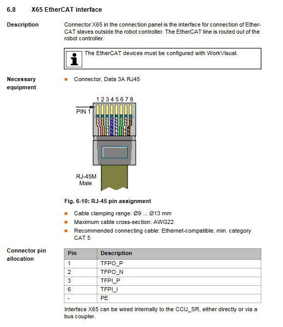
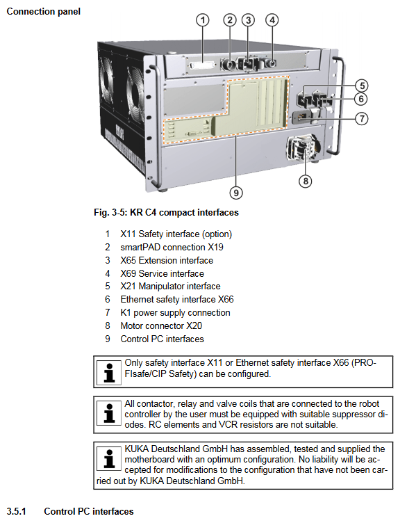
Interfaces: including security interface X11, Ethernet security interface X66, EtherCAT interface X65, service interface X69, etc. X11 and X66 cannot be used simultaneously
Technical data
Category key parameters
Maximum number of axes for basic parameters: 6 axes; Protection level: IP20; Weight: 33kg; Sound Level: Average 54 dB (A)
Power supply requirement rated voltage: 200-230V AC (single-phase/two-phase, with grounded neutral wire); Frequency: 50Hz ± 1Hz or 60Hz ± 1Hz; Rated power: 2kVA; Fuse: 2x16A slow melting
Operating temperature under environmental conditions:+5~+45 ℃ (278~318K); Storage temperature (with battery): -25~+40 ℃; Humidity: 3k3 level (no condensation); Altitude: ≤ 1000m (no capacity reduction), 1000-3000m (5% capacity reduction per 1000m)
Size and installation compatible with 19 “rack (depth ≥ 700mm); 70mm of heat dissipation space needs to be reserved on both sides; Can be installed horizontally or vertically
Cable requirements for smartPAD cable: standard length+2 extensions, total length ≤ 50m; cable length difference for each channel of RDC box ≤ 10m
Safety regulations
core principle
Intended use: Only for operating KUKA industrial robots, prohibited for misuse scenarios such as climbing tools, hyperparameter operation, and use in explosive environments
Compliance standards: comply with EC Machinery Directive (2006/42/EU), EMC Directive (2014/30/EU), EN ISO 13849-1 (PL d/Category 3), etc
Personnel Requirements
Operators need to have advanced knowledge of electrical and electronic systems, robot controllers, and Windows systems. It is recommended to attend KUKA College training
The system integrator is responsible for equipment installation, risk assessment, and compliance declaration; Maintenance and debugging need to be carried out by professional training personnel
Key safety functions
Operation modes: T1 (manual low speed ≤ 250mm/s), T2 (manual high speed), AUT (automatic), AUT EXT (external automatic)
Safety devices: local/external emergency stop button, dual circuit enable switch (3-speed: not pressed/neutral/emergency), safety door interlock, software limit switch, mechanical terminal block
Stop category: Safety STOP 0 (immediate stop), Safety STOP 1 (path keeping stop), Safety STOP 2 (normal deceleration stop)
Scene security measures
Transportation: The controller needs to be transported horizontally to avoid vibration and impact; The robotic arm needs to be placed in the designated transportation position according to regulations
Startup: Wiring, safety devices, and temperature adaptation (to avoid condensation) need to be checked. The new program needs to be tested in T1 mode first
Maintenance/Repair: Power off and lock, post warning labels, wait after power off (some components have residual voltage of 50-780V), and prohibit live operation of high-voltage components
Operation and Startup
Planning and Installation
Installation conditions: 19 “rack depth ≥ 700mm, with 70mm of reserved heat dissipation space on both sides; Only supports grounded neutral wire power supply system
Equipotential connection: A 4mm ² cable (between the controller and the robotic arm) and an additional PE conductor (between the power supply cabinet and the controller) need to be connected
Core Steps for Startup and Debugging
Check for transportation damage to the controller and install and fix it (horizontal/vertical)
Connect motor cable (X20), data cable (X21), smartPAD (X19)
Complete equipotential connection and power connection
Release battery discharge protection (insert X305 connector)
Configure and connect X11 interface (safety circuit)
Release the smartPAD emergency stop button, turn on the main switch, and start the system