KONGSBERG DZ-110/U transmitter safety barrier unit
Core positioning and core functions of the product
Product type: Single channel parallel diode transmitter safety barrier unit, designed specifically for instruments installed in hazardous areas under the Kongsberg brand.
Core function: Provide a safe signal interface and power supply for the two-wire 4-20 mA intrinsic safety transmitter in hazardous areas, serving as an electrical isolation and explosion-proof device between safe and hazardous areas.
Design Highlights: Equipped with exclusive voltage regulation and active current limiting design, it solves the problems of diode leakage and fuse burnout in traditional safety barriers, and is paired with a current mirror amplifier to ensure signal transmission accuracy.
Working principle
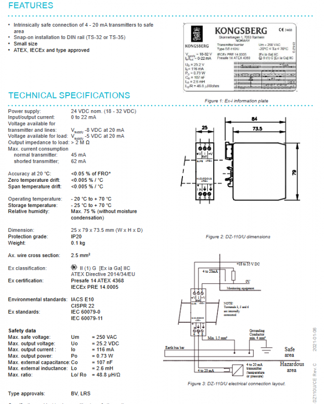
The equipment must be installed in a safe area (such as a control room processing cabinet), and the core achieves electrical safety protection in hazardous areas through “energy limitation+signal replication”. The specific principle is:
Signal transmission: The current signal from the hazardous area transmitter is replicated into a safe side current signal of equal amplitude through a current mirror amplifier, ensuring that the signal is transmitted without deviation;
Leak prevention: Stabilize and limit the voltage applied to the safety barrier module to prevent current leakage from the Zener diode and ensure circuit stability;
Anti melting: Integrated active current limiting function, which limits the circuit current in case of accidental short circuit in the transmitter circuit, preventing the fuse from burning out;
Core function: To fundamentally limit the energy that may occur in the connection circuit of hazardous areas and meet the requirements of intrinsic safety and explosion-proof.
Installation requirements and specifications
The installation of DZ-110/U must strictly follow the intrinsically safe explosion-proof and maritime equipment installation specifications, and all requirements are mandatory. The core rules are as follows:
Installation location and method
Typical installation in the processing cabinet of the control room;
Supports TS-32/TS-35 DIN rail snap fit installation (compliant with DIN46277 standard), requiring the use of end plugs to support the equipment for easy installation.
Definition of wiring terminals
Blue terminals 4, 5, and 6: For intrinsically safe circuits exclusively connected to hazardous areas, color differentiation facilitates wiring identification;
Terminals 2 and 3: Connect the analog input channel of the monitoring system to achieve signal transmission;
Terminal 6: Dedicated grounding terminal, to be connected to the intrinsic safety busbar of the system.
Grounding Specification (Double Grounding Requirement)
Equipment body: Connect terminal 6 to the intrinsic safety busbar of the system through a minimum 1.5 mm ² cable;
Special grounding strip: The intrinsic safety side of the safety barrier must be separately equipped with a grounding/grounding plate, and terminal 3 of each safety barrier must be connected to the grounding plate through a cable of * * ≥ 1.5 mm ² * *.
Special conditions for safe installation
① During the final installation in the cabinet, a minimum separation distance of 50 mm must be maintained between intrinsic safety circuits and non intrinsic safety circuits to prevent safety risks caused by circuit interference;
② The equipment needs to be installed in a cabinet with a protection level of at least IP22, and the protection level can be increased according to the actual installation scenario;
③ The working environment temperature range of the equipment is * * -20 ° C ≤ Ta ≤+70 ° C * *, and the storage temperature is -25 ℃~+70 ℃;
④ The maximum relative humidity in the working environment is 75%, and there is no condensation to prevent damage to the circuit caused by moisture.
Safety instructions: For detailed safety operation and maintenance requirements, please refer to the official document 373874 K-Gauge Ex I Safety Instructions from Kongsberg.
Core product features
Core function: Achieve compliant intrinsic safety electrical connection of 4-20 mA intrinsic safety transmitters from hazardous areas to safe areas, with no deviation in signal transmission;
Flexible installation: Supports TS-32/TS-135 DIN rail snap fit installation, compatible with different rack rail specifications, and does not require additional fasteners for installation;
Compact size: The overall size is only 25 × 79 × 73.5 mm, and the weight is only 0.1kg, greatly saving the installation space of the control room cabinet;
Excellent performance: Built in voltage regulation and active current limiting design, high precision, small temperature drift, circuit stability and explosion-proof safety far exceed basic safety barriers;
Complete certification: ATEX, IECEx international explosion-proof certification, BV, LRS maritime classification society type certification, in compliance with maritime industry standards.
Key technical specifications
The core specifications of DZ-110/U, including electrical, physical, intrinsic safety explosion-proof, and precision drift, have clear standards. The summary table of core parameters is as follows:
Specification category specific parameters
The power supply is rated at 24 VDC and compatible with a wide voltage range of 18-32 VDC
Current and voltage input/output current: 0~22 mA; transmitter/line available voltage at 20mA: Vsupply-8 VDC; Load available voltage at 20mA: Vsupply-5 VDC
Normal current consumption: 45 mA for transmitter operation; 62 mA for transmitter short circuit
Output impedance to load output impedance:>2 M Ω
Accuracy and temperature drift at 20 ℃:<0.05% FRO; Zero temperature drift:<0.005%/℃; Range temperature drift:<0.005%/℃
Physical dimensions: 25 × 79 × 73.5 mm (width × height × depth); Weight: 0.1 kg; Terminal adapter wire diameter: 2.5 mm ²; Equipment self-protection level: IP20
Environmental parameters operating temperature: -20 ° C~+70 ° C; Storage temperature: -25 ° C~+70 ° C; Relative humidity: ≤ 75% (no condensation)
The maximum safe voltage of intrinsic safety parameters is Um=250 VAC; Maximum output voltage Uo=25.2 VDC; Maximum output current Io=116 mA; Maximum output power Po=0.73 W; Maximum external capacitance Co=107 nF; Maximum external inductance Lo=2.6 mH; Lo/Ro=48.8 µH/Ω
Certification standards
Explosion-proof certification
Explosion proof grade: II (1) G [Ex ia Ga] IIC (highest level intrinsic safety explosion-proof for maritime hazardous areas);
ATEX Directive: 2014/34/EU, certification number Presafe 14 ATEX 4368;
IECEx certification: Number IECEx PRE 14.0005;
Explosion proof standards: IEC 60079-0, IEC 60079-11.
Maritime and Environmental Certification
Classification society type certification: BV (French Classification Society), LRS (Lloyd’s Register of Shipping);
Environmental standards: IACS E10 (Maritime Equipment Environmental Standard), CISPR 22 (Electromagnetic Compatibility Standard).