GE Fanuc 90-30 PLC Hardware Guide
In the field of industrial automation, GE Fanuc’s (now part of Emerson Automation Solutions) Series 90-30 programmable logic controllers (PLCs) have become the backbone of control systems due to their modular design, powerful processing capabilities, and flexible scalability. This guide is based on the “Series 90-30 PLC Installation and Hardware Manual” (document number GFK-0356Q), which deeply analyzes the hardware architecture, installation specifications, CPU characteristics, and maintenance points of this series of PLCs, aiming to provide a detailed technical reference for automation engineers.
Overview of System Architecture and Components
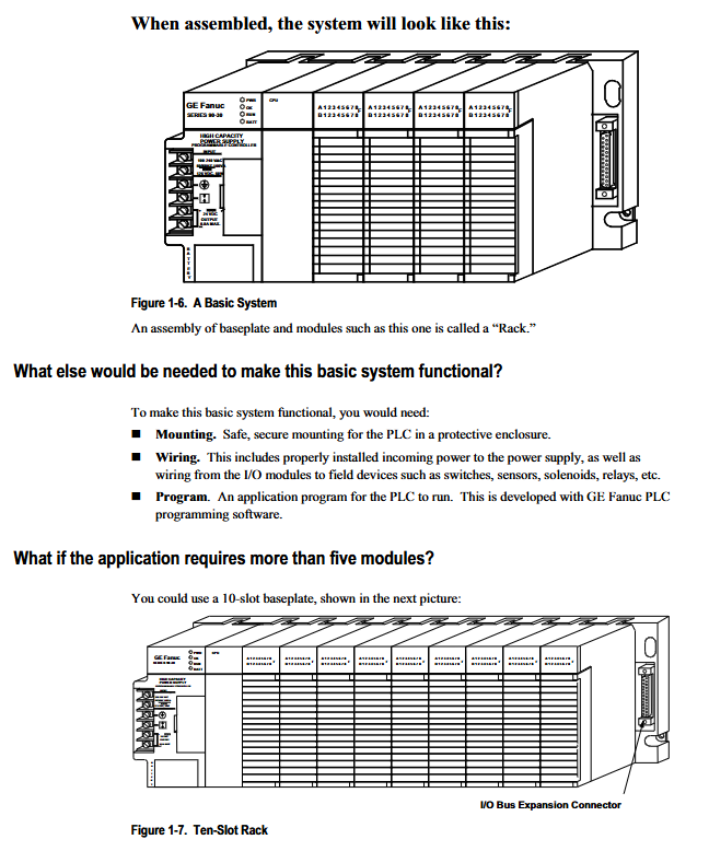
The core advantage of the Series 90-30 PLC system lies in its modular architecture. A basic PLC system consists of six core components: motherboard, power module, CPU module, I/O module, option module, and connecting cables.
1.1 Bottom plate and rack configuration
The backplane is the physical foundation of the PLC system, carrying all modules and achieving electrical connections through the backplane bus. The Series 90-30 motherboard is divided into three types: CPU motherboard, expansion motherboard, and remote motherboard, each with two size specifications of 5 slots and 10 slots.
CPU motherboard: As the main control core of the system, a CPU module must be installed. It is assigned as rack number 0 by default. According to different designs, CPU baseboards are divided into “embedded CPU baseboards” (such as models 311, 313, 323, where the CPU is soldered onto the backplane) and “modular CPU baseboards” (where the CPU is a pluggable module).
Expansion and remote backplane: When the system requires more I/O points beyond the capacity of the main backplane, expansion or remote backplane needs to be used.
Expansion board: Suitable for configurations within 50 feet (approximately 15 meters) of the CPU board, with fast communication speed.
Remote Base Plate: Suitable for configurations within 700 feet (approximately 213 meters) of the CPU base plate. The remote backplane integrates an isolation circuit internally to prevent grounding circuit issues during long-distance transmission.
Rack number setting: Expansion and remote baseboards must have a unique rack number (1-7) set through DIP switches and must not conflict with the CPU baseboard (Rack 0).
1.2 System Distance Limitations and Expansion
Standard I/O bus expansion cables (such as IC693CBL300 series) are used to connect various baseboards. If the application requires a physical distance exceeding 700 feet, a communication option module must be introduced. For example, the Genius Bus Controller (GBC) can extend communication distance up to 7500 feet, while RS-485 serial communication can reach up to 4000 feet.
Hardware installation and wiring specifications
Proper installation and wiring are prerequisites for ensuring the long-term stable operation of PLC systems. The manual provides detailed specifications for every aspect from module insertion and removal to system grounding.
2.1 Installation and disassembly of modules
All Series 90-30 modules adopt a plug-in design.
Installation steps:
Ensure that the power is disconnected (Warning: Live plugging may cause equipment damage or personal injury).
Align the pivot hook at the top of the module with the guide slot on the upper part of the base plate.
Rotate the module downwards until the bottom connector is inserted into the backplane socket and the release lever at the bottom is locked in place.
Terminal board operation: The I/O module is equipped with a detachable terminal board for easy pre wiring. When replacing a module, there is no need to rewire, just plug the terminal board into the new module. Some models (such as IC693MDL730F and later versions) are equipped with fastening screws to prevent loosening in vibration environments.
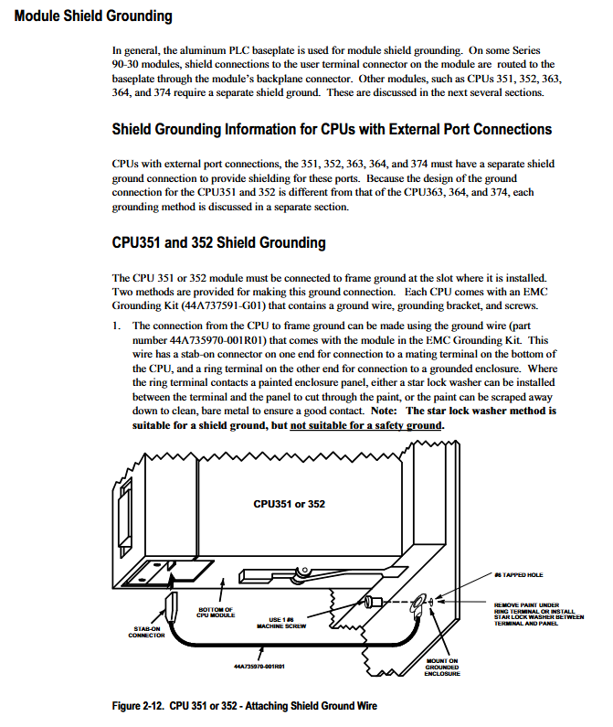
2.2 System grounding strategy
Grounding is the key to anti-interference of PLC. The manual emphasizes the need to follow a “tree like” grounding structure, where all grounding wires converge to a central grounding point.
Bottom plate grounding: The metal back plate of the bottom plate must be grounded. Suggest using AWG # 12 (3.3 mm ²) or larger wire to connect to the mounting hole at the bottom of the motherboard. For painted control cabinets, the installation point paint must be scraped off to ensure metal contact.
Shielding grounding: For analog modules and communication cables, the shielding layer should only be grounded at the end with the highest noise (usually the field equipment end), and the other end should be suspended and insulated to cut off the grounding loop.
2.3 Wiring Classification and Routing
To reduce noise coupling, wiring should be strictly classified:
AC power cord: including PLC power input and other AC equipment circuits.
Discrete output line: usually drives inductive loads and produces noise spikes when disconnected.
DC input and analog signal lines: belong to low-level signals and need to be physically isolated from strong current lines. When crossing, it should be done at a right angle (90 degrees).
Communication lines, such as Genius bus or serial cables, should be kept away from power lines.
2.4 Special Installation of Floating Neutral Point (IT System)
In an ungrounded power system (IT system), the neutral wire is not connected to the protective ground. At this point, the factory jumper between terminals 3 and 4 on the power module terminal board must be removed, and an external surge protection device (such as MOV) must be installed between L1 and L2 to prevent damage to the power module.
Detailed explanation of power supply module
The power module is located in a dedicated slot on the leftmost side of the motherboard, providing stable DC voltage for the CPU and I/O modules. Series 90-30 power supplies are divided into two categories: AC/DC input and pure DC input.
3.1 AC/DC input power supply
Standard Type (IC693PWR321): Input range up to 85-264 VAC or 100-300 VDC, total output power 30W. Provides+5 VDC (15W),+24 VDC isolated power supply (20W), and relay power supply (15W).
High Capacity Type (IC693PWR330): Similar in specifications to PWR321, but with an increased+5V output capability of 30W, suitable for systems with a large number of CPUs and expansion modules.
3.2 DC input power supply
IC693PWR322: Supports 24/48 VDC input.
IC693PWR328: Supports 48 VDC input.
High capacity type (IC693PWR331): 24 VDC input, allowing+5V output up to 30W, suitable for high load requirements.
3.3 Status indicator lights
All power modules are equipped with four LED indicator lights for quick diagnosis:
PWR: Green, indicating that the power supply is working properly.
OK: Green, always on when the CPU is running normally.
RUN: Green, the PLC is constantly on when in running mode.
BATT: Red, lights up when the backup battery is low, indicating the need for immediate replacement.
Central Processing Unit (CPU) Core Features
CPU is the brain of PLC. Series 90-30 offers a complete product line from economical embedded CPUs to high-performance modular CPUs.
4.1 Embedded CPU (Models 311, 313, 323)
This type of CPU is integrated on the backplane of the motherboard, with lower cost and suitable for small control systems.
Limitations: Expansion or remote backplane is not supported, and the maximum number of I/O points is limited by the number of backplane slots (160 or 320 points). Real time clock is not supported.
Memory protection: The backup battery is located in the power module. If the power is unplugged, the battery connection will be disconnected, and the memory will only be maintained by the supercapacitor on the backplane for about 1 hour.
4.2 Modular CPU (Models 331-374)
Modular CPU is inserted into Slot 1 slot, supporting system expansion and powerful functionality.
CPU331/340/341: Basic type processor, supporting floating-point operations (firmware support required), with memory ranging from 16KB to 80KB.
CPU350/360: Equipped with 80386EX processor, 25 MHz main frequency, supporting larger I/O capacity (2048 points) and configurable memory.
CPU351/352/363: Integrated with additional serial ports (Port 1 RS-232, Port 2 RS-485) for easy connection to programmers and HMI. The CPU352 is equipped with a built-in hardware floating-point coprocessor, which has extremely fast computation speed.
CPU364/374: Flagship product with integrated Ethernet interface. CPU364 provides 10Base-T and AAUI interfaces; The CPU374 is equipped with a 10/100Base-T switch, providing two Ethernet ports, supporting Ethernet Global Data (EGD), with a clock speed of up to 133 MHz and a memory capacity of 240KB.
4.3 Memory and firmware
Memory types: RAM (working memory, volatile), EPROM (ultraviolet erase), EEPROM (electrical erase), Flash (flash memory, firmware storage, and user program backup).
Firmware upgrade: For CPUs (such as 350+) that use Flash to store firmware, software upgrades can be performed by connecting to a PC through a serial port; Early models require replacement of EPROM chips.
Memory backup and battery maintenance
Preventing program loss is of utmost importance in maintenance work.
5.1 Lithium battery (IC693ACC301)
The lithium battery located at the bottom of the power module provides power to the CMOS RAM.
Lifespan: At room temperature, the lifespan is about 5 years when connected to a power source; If there is a long-term power outage, the lifespan is about 1 year (depending on the CPU model).
Replacement procedure: Even if the PLC is in a power-off state, as long as the BATT light is on, the battery must be replaced before the power is cut off. When replacing, the supercapacitor on the power module can provide a buffer time of about 20 minutes, allowing for live replacement.
5.2 Supercapacitors
Both embedded and modular CPUs are equipped with supercapacitors. When the power module is unplugged or the battery fails, the capacitor can maintain the memory content for at least 1 hour (if the PLC has just been powered off) or 20 minutes (if the battery has failed). This provides a valuable emergency window for maintenance.
5.3 Battery free operation
For applications that do not require frequent storage of critical data, the CPU can be configured to boot from Flash or EPROM. Set the configuration parameter to “Pwr Up Mode: RUN; Logic/Cfg: PROM”, and the program will be automatically loaded from PROM every time power is turned on.
Input/Output (I/O) Module Configuration
The I/O modules of Series 90-30 are divided into two categories: discrete and analog, and support high-density configurations.
6.1 Discrete I/O
Standard density (≤ 16 points): Equipped with detachable terminal boards, supporting direct wiring or terminal block wiring.
High density (32 points): Early models used 50 pin connectors that needed to be paired with terminal boards (such as Weidmuller # 912263); The new model adopts dual 24 pin connectors and supports TBQC (Terminal Block Quick Connect) components, significantly saving wiring time.
Relay output protection: When driving inductive loads, RC networks (AC loads) or reverse diodes (DC loads) must be connected in parallel at both ends of the load to prevent surge voltage from damaging the contacts.
6.2 Analog I/O
Provide voltage (0-10V) and current (4-20mA) signal processing. Wiring must use twisted pair shielded cables, and the shielding layer must be grounded at one end. TBQC is not recommended for analog modules as it does not meet the shielding requirements.
6.3 Digital Valve Driver Module (IC693DVM300)
Special function module, providing 4-channel 24VDC output with a maximum current of 1.6A, directly drives the valve without the need for power supply through the PLC backplane.
Option module and network communication
Series 90-30 expands its control capabilities through rich option modules.
7.1 Genius Communication Module
GCM (IC693CMM301): Implement global data communication between Series 90-30 and other GE PLCs.
GBC (IC693BEM331): Interface Genius I/O bus, connects remote I/O stations, field control stations, etc., supports up to 31 devices, and has extremely high transmission rates.
7.2 Motion Control Module
APM (IC693APU301/302): Single axis/dual axis positioning module, supporting standard mode and following mode.
DSM302/314: High performance digital servo module, integrated DSP control, supporting electronic cam, high-speed output, and multi axis synchronization.
7.3 Ethernet interface
CPU364/374 has built-in Ethernet ports and supports SRTP and EGD protocols. For other CPUs, an independent Ethernet module (IC693CMM321) can be selected.
Maintenance and troubleshooting
8.1 Status LED Diagnosis
In addition to the LED of the power module, each I/O module and CPU panel are also equipped with LED. For example, the “PS PORT” on the CPU panel indicates the serial communication status; The “EOK”, “LAN”, and “STAT” of Ethernet CPUs indicate the network status.
8.2 Fault History
The CPU will automatically record fault information, and the fault table can be viewed through programming software.
8.3 Preventive maintenance
Regularly check whether the wiring terminals are loose.
Monitor the ambient temperature to ensure good heat dissipation inside the cabinet (vertical installation is beneficial for heat dissipation).
Replace the backup battery on time, it is recommended to replace it once a year or during the annual maintenance period.