IbaLink-SM-128V-i-2O VMEbus interface board
Product basic information
R&D and Certification: Produced by IBA AG in Germany, compliant with European standards and CE certification, manual version Issue 2.5, hardware version iterated from V1.0 (2000) to V1.3 (2007), order number 14.131000;
Product positioning: The full name is ibaLink-SM-128V-i-2O VMEbus Interface Board, abbreviated as SM128V, which is a multifunctional bidirectional interface board suitable for VMEbus compatible PLC and computer systems. Its core is used for data acquisition, process monitoring, and control system applications (such as ibaLogic SoftPLC);
Copyright and documentation: Unauthorized dissemination and copying of the manual are prohibited. The latest version can be downloaded from the official website www.iba-ag.com.
Core Key Features
SM128V is a passive VMEbus board with no active bus access behavior. Its core features are as follows:
Transmission link: Channel 1 is a bidirectional fiber optic link (64 analog+64 digital input/output), and Channel 2 is a unidirectional fiber optic link (64 analog+64 digital output), both supporting 3.3Mbps speed and 1ms synchronous message transmission;
Cascading capability: Channel 1 supports daisy chain cascading of up to 8 SM128V cards, with signals allocated through range/address switches;
VMEbus compatibility: compatible with VME32/VME64 systems, supports A24/A32 address mode (A40 MD32 can be customized), data formats include D08 (D0)/D16/D32, only supports non privileged data access mode;
Address and power supply: 5V power supply provided by VMEbus, maximum current 1A, occupying 256 kByte of VMEbus address space;
Device compatibility: Compatible with ibaFOB-io/4i (- S)/4o, ibaPADU-8-IO series, ibaNet750-BM series and other iba devices, RJ11 interface can connect ibaPCMCIA-F devices.
System operation requirements
The hardware, software, and control system of SM128V must meet the following conditions:
Category specific requirements
Hardware 1 IBM compatible computer: Pentium IV 1GHz, 256MB RAM, 20GB HD and above;
2. The computer requires at least one ibaFOB-io/ibaFOB-4i (- S) board;
3. VME rack: 32/64 bits (modified SM128V-16 compatible with 16 bits)
Software 1 Operating systems: Windows NT 4.0 (SP6), 2000, XP;
2. Supporting software: ibaPDA version>3.11 (compatible with SM128V and ibaLink-SM-64-io)
The control system needs to have compatible hardware interfaces, which have been adapted to ALSPA CP80/A800, ALSPA C80 HPC/HPCi, GE 90/70, Simatic TDC, etc
Installation and disassembly specifications
Core premise: Follow the operating standards for electrostatic sensitive equipment throughout the operation. Before contacting the board, it is necessary to ground and discharge to avoid touching the connector. The VMEbus rack power must be turned off before installation/disassembly.
Installation steps: Unpack → DIP switch preset → Slide the board into the VME slot (align the guide pin with the slot) → Tighten the buckle → Tighten the front panel screws;
Dismantling steps: Power off → Loosen the panel screws → Open the buckle to release the backboard connection → Pull out the board;
Special requirement: The GE 90/70 system rack has no guide pin slot. If the board is not customized, the guide pin must be removed before installation.
Equipment structure and operating components
The operating components of SM128V are divided into front-end panel and onboard components, with clear functional division:
Front panel components (core functions)
Component Name Quantity/Identification Core Function
Fiber optic connectors TX/RX (5/6) and TX (10) 5/6 are Channel1 bidirectional ST type interfaces, and 10 is Channel2 unidirectional ST type interface
RJ11 connectors Channel1 (11) and Channel2 (12) are unidirectionally connected to ibaPCMCIA-F, synchronously transmitting data with the corresponding fiber channel
Mode switch (3) Mode 0=normal/cascade mode, 8=point-to-point mode (cascade prohibited)
Range switch (7) Range 1-8, allocate channel numbers in units of 8 signals, maximum 8 × 8=64 channels
Address switch (8) Address 1-8, defines the starting position of local data in the daisy chain message
Reset button (2) Reset the card, which may interrupt the host bus access during reset
The status LEDs (4/9) Run (green), Link (yellow), and Error (red) indicate the power supply, data transmission, and equipment failure status, and automatically turn off after the Error is restored
Onboard components
DIP switch: located at the bottom of the board, default configuration 0xE0000000, used to set interrupts, data byte order (big/small end), data format (integer/REAL), VMEbus address mode (A24/A32), and starting address;
X6 service interface: D-sub 9-pin interface, used for loading firmware, only valid for TxD (2), RxD (3), GND (5);
DIL switch: auxiliary configuration of VMEbus starting address and exclusive parameters for each control system.
Key Configuration Description
The configuration core of SM128V consists of onboard DIP switches and front-end panel switches, with dedicated configuration solutions for different control systems:
General DIP switch function: can set test mode, interrupt, byte order (CH1/CH2 independent), data format (integer/REAL), VME address mode, memory address bits (A18-A31), default to disable test mode and interrupt, CH1/CH2 for small terminal, integer format, A32 mode;
VMEbus starting address: set by DIP switch A18-A31 bits, the last four digits of the hexadecimal address are fixed to 0, and the default starting address is 0xE0000000;
Front end switch coordination: In non cascade mode, set Range to 8 and Address to 1; Set 1-8 according to signal allocation requirements in cascade mode;
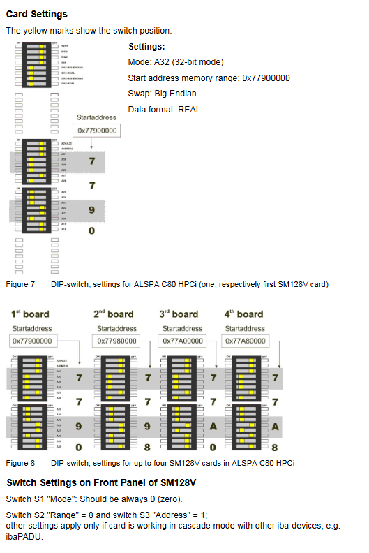
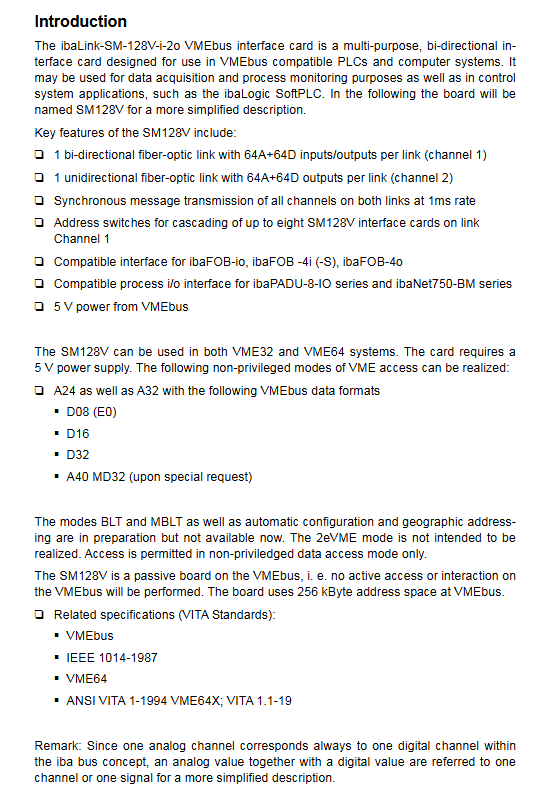
Exclusive control system configuration: Customized DIP switches and front-end switch settings are provided for the ALSPA series, GE 90/70, and Simatic TDC. For example, the ALSPA C80 HPCi defaults to A32 mode, big end, and REAL format, with a starting address of 0x7790000, and ALSTOM reserves 4 VME addresses for it, each occupying 512kByte (actual use of 256kByte).
Five working modes
SM128V supports 5 typical working modes and is suitable for different industrial measurement and control scenarios. The core parameters are as follows:
Peer to Peer mode: Mode set to 8, 2 SM128V directly connected, exchanging 64A+64D signals every 1ms without the need for additional accessories/software, with one output being the input of the other;
IbaPDA mode: Only using fiber Tx interface, connected to ibaFOB-io/4i (- S) input, transmitting a total of 128A+128D signals. ibaPDA ≥ 5.20 version supports signal scaling, while old versions only support physical units;
IbaLogic mode: bidirectional interaction, Channel1 Rx connected to ibaFOB-io/4o output (receiving 64A+64D), Tx connected to ibaFOB input (sending 128A+128D), requiring dedicated FOB input/output resources;
Cascade mode: Set Mode to 0 and cascade up to 8 SM128V daisy chains. Allocate 64 total signals according to Range/Address, avoiding data coverage caused by address/range overlap;
Process I/O mode: As a bus extender for VME PLC, it connects ibaPADU-8/ibaNet750-BM series I/O devices, and Channel1/2 can connect 8 ibaPADU-8-O devices each, supporting mixed use of cascade/IO modes.
Detailed definition of VMEbus interface
The VMEbus interface of SM128V includes three parts: address space partitioning, pin definition, and data format, which are the core of interaction with the VME system:
Address space (256kByte): Divided by function into hardware control area (0000H-003FH), version information area (0040H-007FH), analog/digital data area (6000H-6FFFFH), etc., where the heartbeat counter (80H) increments every 0.8 seconds and the LED status register (E4H) can read the device’s operating status;
Pin definition: Using J1/J2 160 pin connectors (VME+standard), J1 is responsible for basic signals such as D0-D15 and A16-A23, while J2 is responsible for extended signals such as D16-D31 and A24-A31, both providing+5V power supply and GND grounding;
Data format: Supports large/small byte order (DIP switch settings), analog signals can choose integer/IEEE floating point, digital signals support single bit or 8-byte bit mask formats, and both formats require resetting unused registers to avoid conflicts.
Technical Specifications
The physical, electrical, and environmental parameters of SM128V are shown in the following table:
Category parameter indicators
Environmental parameters Operating temperature: 0~50 ℃; Storage/transportation temperature: -25~70 ℃; Humidity: Class F, no condensation allowed
Physical specification installation: 1 standard VME slot; Front panel: 6U/4HP; Size: 233.6mm × 160mm (9.2 “× 6.3”); Weight: Approximately 1kg (including packaging/documentation)
Electrical parameter power supply: VMEbus 5V DC; Maximum current: 1A; no watchdog; Fiber optic without isolation
Transmission parameter fiber speed: 3.3Mbps; Maximum transmission distance without relay: 2000m; cooling method: natural convection