SEW EURODRIVE DFS/DFY series synchronous motors
Overview
Name: DFS/DFY Synchronous Motors Operating Instructions
Core purpose: To guide the safe installation, wiring, starting, maintenance, and troubleshooting of DFS/DFY series synchronous motors (with or without brakes), including the brake modification process
Product range:
Model: DFS56 (with terminal box), DFY71/90/112 (with terminal box/plug)
Configuration: No brake, with brake (.. B suffix), with AV1Y absolute encoder/TF/TH thermal protection/VY cooling fan
Key limitations:
Storage environment: dry, dust-free, vibration free, temperature -25~+40 ℃
Operating environment: No harmful media such as oil, acid, gas, etc., humidity ≤ 85% (no condensation)
Installation height: ≤ 1000m, if it exceeds 1000m, the capacity needs to be reduced (ratio not specified)
Safety and Installation Fundamentals
Safety operation requirements
Specific requirements for safety categories
Only professional personnel are authorized to install, wire, start, and maintain the operation qualification
Compliance with regulations must comply with project documents, controller manuals, and national/regional safety regulations
Risk protection: Avoid live working and shaft end impact, and prevent contact with high-temperature surfaces (>65 ℃)
Preparation before installation
Long term storage preprocessing (execution required for overdue storage):
Measure the insulation resistance of the winding (U/V/W to the casing) and measure the voltage at 500V
The insulation resistance must meet the temperature corresponding limit (≥ 1M Ω at 20 ℃, ≥ 0.5M Ω at 40 ℃)
The terminal box/plug needs to be clean and dry, with intact seals and tightened threads
Tool preparation: standard tools, crimping tools, end connectors (DIN 46228 Part 1, E-Cu material), disassembly tools
Installation specifications
Mechanical installation:
Installation surface: horizontal, vibration free, anti torsion rigid support
Axis alignment: Avoid bearing force on the axis, follow the allowable cantilever load and axial thrust
Cleaning requirements: Rust inhibitor should be removed from the shaft end and flange (solvents that corrode bearings are prohibited)
Vertical installation: Motors with VY cooling fans require protective covers to prevent foreign objects/liquids from entering
Installation in special environments (humid/outdoor):
Terminal box cable entry facing downwards
Apply sealant to the sealing joint of the threaded cable and tighten it securely
Clean the sealing surface of the terminal box, bond the gasket on one side, and replace the aging gasket
Repair the anti-corrosion coating if necessary
Electrical connection
Motor wiring
Model wiring method, core wiring points
DFS56 (terminal box) cage clamp connection power: U/V/W/PE; Signal: solver (R1/R2/S1-S4), TF/TH
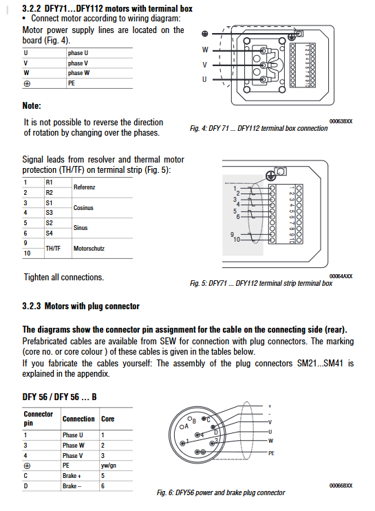
DFY71-112 (terminal box) terminal block connection power: U/V/W/PE; Signal: solver (R1/R2/S1-S4), TF/TH
Prefabricated cables/custom cables with plugs, power core wires 1-3 (U/V/W), PE (yw/gn color); Signal core wires are defined by pins
Key note: Do not change the motor direction through commutation
Brake connection
Model Power Supply Specification Control Method Cable Requirements
DFS56.. B 24VDC ± 10% direct control 4-core cable, connected according to terminal definition
DFY71-112. B 110/230/400VAC or 24VDC switchgear with BM series rectifiers (BMP/BMH/BME) or BSG control unit 4-core cables, requiring simultaneous disconnection of AC/DC circuits (for elevator applications)
Contactor requirements: AC3 level contactors (EN 60947-4-1) must be used, suitable for DC voltage and high current loads
attachment link
AV1Y absolute encoder:
Connection distance: up to 100m
Adaptive controller: MOVIDYN ® (APA12 interface) MOVIDRIVE ® (DPA11A/DIP11A tab)
Cable requirements: twisted pair shielded cable, with both ends of the shielding layer extensively grounded
TF/TH thermal protection:
TF (PTC Thermistor): Compliant with DIN 44082, normal temperature resistance 20-500 Ω, over temperature>4000 Ω
TH (Embedded Thermostat): series connection, over temperature disconnect, maximum voltage 60VAC/DC
VY cooling fan: 3-core cable, connecting phase, neutral wire PE, Connect the plug pins according to the definition
EMC compliance requirements
Signal cable: The resolver and TF/TH signals use twisted pair shielded cables, with each pair of signals twisted separately
Cable separation: Separate the brake cable from the power cable for wiring, or shield the power cable
Shielded connection: The shielding layer is grounded at both ends to ensure large-area contact
Start up and maintenance
startup process
Starting premise:
All connections are correct and secure, and the plugs are anti loose
The motor protection function (TF/TH, overcurrent) has been activated
The drive system has no jamming or safety hazards
Insulation inspection has been completed after long-term transportation/storage
Start operation:
Follow the accompanying servo controller (MOVIDYN) ®/ MOVIDRIVE ®) Instruction Manual
Suggest using software tools (MOVITOOLS, MD_SCOPE) to assist with startup
maintenance
Maintenance cycle: There is no fixed cycle, it needs to be formulated according to the application scenario, and regular visual inspections are required
Brake maintenance (DFY71-112. B):
Maintain project requirements/steps
During the inspection and release of the working air gap, the pressure plate stroke is 0.25-0.8mm, which can be measured using screws or disassembled plugs
Brake disc replacement: 1. Remove the plug and gasket; 2. Use auxiliary screws to pull back the pressure plate; 3. Disassemble the coil body; 4. Replace the brake disc (to avoid oil contamination); 5. Reinstall and tighten
Adjust the braking torque and replace the brake spring as needed after disassembly (symmetrical installation), refer to Appendix Table 4
Encoder maintenance:
Before disassembling the brake, it is necessary to remove the AV1Y encoder to avoid damaging the coupler
Ensure that the coupler has no axial tension and the shaft runout is ≤ 0.05mm during reassembly
Bearing replacement: Only SEW trained personnel can operate (requires recalibration of the resolver)
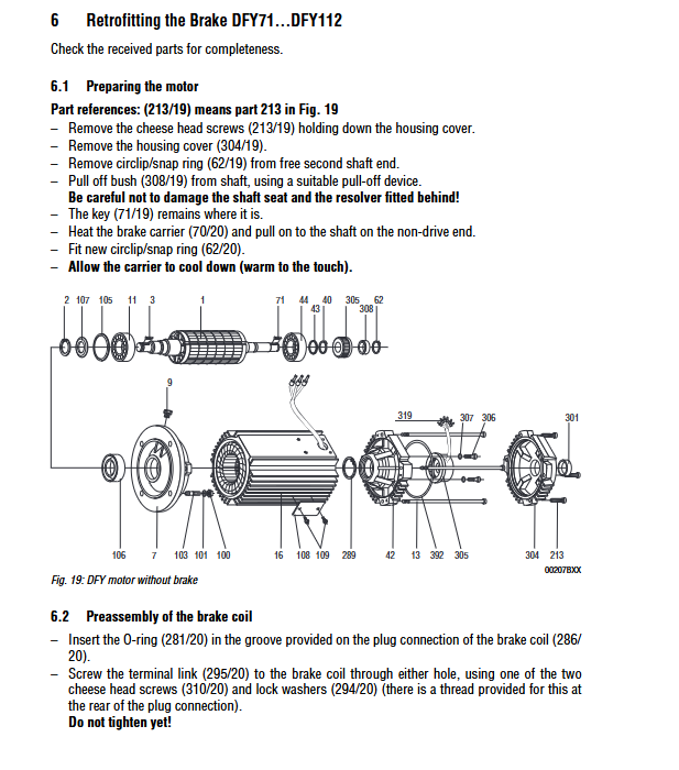
Brake modification (DFY71-112 without brake → with brake)
Core steps:
Motor preparation: Remove the end cover, retaining spring, and shaft sleeve, heat up the brake bracket and install it
Pre installation of brake coil: Install O-ring, terminal link, insert coil body and lock
Brake pre installation: Install parallel pins, brake springs (according to torque requirements), and pressure plates
Motor installation: Install the retaining spring, brake disc, intermediate ring, and tighten the coil body
Manual release installation: Install the release yoke and lever, adjust the gap by 2mm
Electrical connection: Connect according to section 3.3 and test the braking action
Troubleshooting
Common motor faults
Possible causes and solutions for the fault phenomenon
Unable to initiate circuit breakage, fuse failure, controller malfunction/wiring error. Check and repair the circuit; Replace the fuse; Check the controller and wiring
Difficulty in starting the controller due to incorrect settings, overload and reconfiguration of the controller; Check the load and reduce it
Steering error controller control error check controller setting value, swap setting value circuit
Reduce load due to motor overheating, overload, insufficient cooling, and high ambient temperature; Clean the cooling channel/install a cooling fan; Reduce the ambient temperature
Damaged bearings with abnormal noise, unbalanced rotating parts, and re centering; Check the driven equipment; replace the bearing
Common brake malfunctions
Possible causes and solutions for the fault phenomenon
Unable to release voltage error, control unit malfunction, air gap out of tolerance, coil short circuit, apply nameplate specified voltage; Replace the control unit; Adjust the air gap/replace the brake disc; Replace the brake
The braking delay is changed from only cutting off the AC circuit to cutting off both the AC and DC circuits simultaneously
Abnormal braking torque, incorrect spring selection, brake disc wear, replacement of springs as required; Replace the brake disc
Brake noise causing gear wear and incorrect controller settings due to startup impact. Check the drive configuration; Re optimize controller parameters
Key technical data
Core parameters of brake system
Motor model Maximum braking torque (Nm) Minimum braking torque (Nm) Coil resistance (24VDC, Ω)
DFS56M/B – 2.5 59
DFY71S/B 6 3 3.6
DFY90S/B 20 12 2.5
DFY112L/B 90 35 1.8
Cable specifications
Connecting object, core wire section, cable outer diameter (mm), stripping length (mm)
Motor power (DFY71) 4 × 1.5mm ² 13.5 7 ± 0.5
Resolver signal 4 × 2 × 0.22~0.56mm ² -5 ± 1
AV1Y encoder 3 × 2 × 0.24~1mm ² 8 4