SEW-EURODRIVE MOVIDRIVE ® MDX60B/61B series frequency converter system
SEW-EURODRIVE MOVIDRIVE ® The MDX60B/61B series frequency converter system manual covers the core product system (MDX60B/61B basic unit, MDR60A/61B regenerative power unit), technical parameters (0.55-315kW power, 400/500V/230V voltage, 0-7 seven sizes), control modes (VFC/CFC/SERVO), rich tabs (encoder/bus/IO expansion class), installation and start-up, operation and maintenance, and compliance certification (UL/CHUL/AAC/RCM), integrated with IPOSPLUS ® Positioning control, supporting multi bus communication and regenerative energy feedback, suitable for industrial multi scenario driving, emphasizing modular design and EMC/safety compliance requirements.
Product System and Core Technical Parameters
Basic Unit (MDX60B/61B)
Model Core Differences Power Range Size Coverage Expansion Capability
MDX60B without encoder feedback 0.55-45kW (400/500V) 0-4 without option slot
MDX61B supports encoder/servo control of 0.55-315kW (400/500V); 1.5-37kW (230V) 0-7 size 0 (2 slots); 1-7 (3 slots)
Core electrical parameters (400/500V series example):
Size Rated output current (IN) Recommended motor power (constant load) Minimum resistance of braking resistor (RBWmin) Cooling air consumption
0S 2A 0.55kW 68Ω 3m³/h
3 32A 15kW 15Ω 180m³/h
7 300A 160kW 1.1Ω 1200m³/h
Comparison of control modes:
The control mode is suitable for motor encoders and requires core characteristics
VFC asynchronous motor optional voltage control, 150% torque (above 0.5Hz)
CFC asynchronous/synchronous servo motor requires current control, 160% torque, servo level performance
SERVO synchronous servo motor requires high-precision positioning and zero speed torque maintenance
Regenerative power supply unit (MDR60A/61B)
Core function: Replace braking resistors, feedback regenerative energy to the power grid, and reduce control cabinet thermal load
Key parameters:
Model rated power compatible with MDX model DC bus current (IDC)
MDR60A0150 15kW 0005-0150 35A
MDR61B2500 250kW 0005-2500 407A
Advantages: Simplified installation when multiple frequency converters are shared, reducing the space occupied by braking resistors
General Technical Parameters
Environmental conditions: working temperature 0-50 ℃ (100% load), capacity reduction of 2.5%/K at 40-50 ℃, capacity reduction of 3%/K at 50-60 ℃; storage temperature -25~70 ℃
Protection level: basic unit IP00/IP10/IP20 (depending on size and accessories); DBG60B keyboard IP40; DBM60B shell IP65
Safety compliance: STO function complies with EN 61800-5-2, performance level d (Cat. 3); Overvoltage category III, pollution level 2
Key tabs and accessories
Encoder tab (core function: motor/external position detection)
Tab model supports encoder type, core characteristics, applicable scenarios
DEH11B HIPERFACE ®、 Sine cosine, TTL dual input (motor+external), maximum 200kHz ordinary positioning control
DER11B rotary transformer, dedicated for external encoder rotary transformer, with a maximum cable length of 100m for servo motor drive
DEU21B incremental/absolute/SSI/OnDet multi protocol compatibility, pulse range 2-4096 for complex positioning scenarios
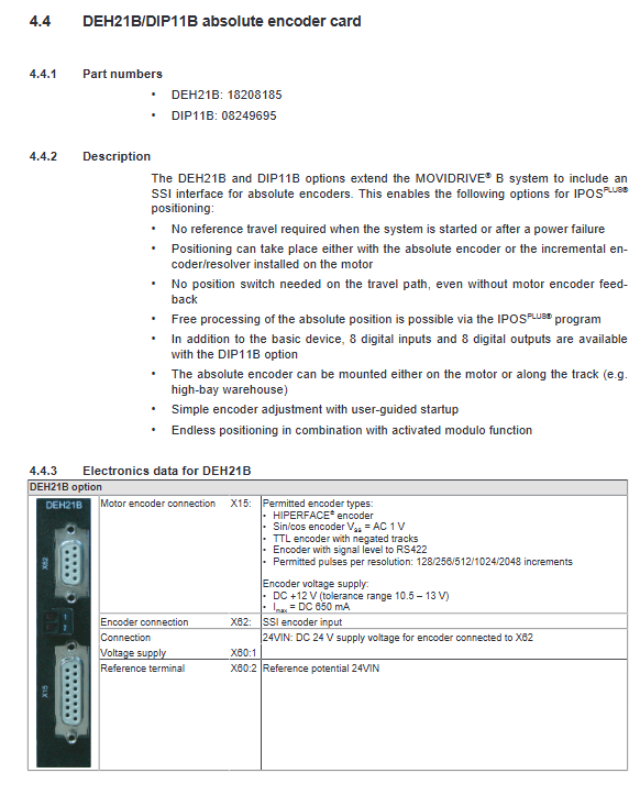
DEH21B/DIP11B SSI absolute encoder does not require reference operation, with 8DI/8DO extended high-precision positioning (such as stereo warehouse)
Bus interface tab (core function: communication with upper system)
Mainstream industrial bus:
Bus Type Tab Model Baud Rate/Rate Maximum Node Count Core Features
PROFIBUS DFP21B 9.6k-12Mbaud 125 supports DP-V1 and GSD file adaptation
PROFINET DFE32B 100Mbaud – with web server, supports RT
EtherCAT ® DFE24B 100Mbaud – Automatic Addressing, 10 sets of process data
EtherNet/IP ™ DFE33B 10/100Mbaud – Supports DHCP, Modbus TCP compatibility
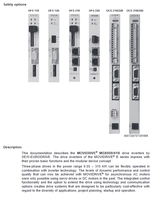
Safety bus options: DFS11B (PROFIBUS+PROFIsafe), DFS21B (PROFINET+PROFIsafe), meet functional safety requirements
Expansion and Adaptation Tab
DIO11B: IO expansion board, including 8DI+8DO+1AI+2AO, suitable for complex IO requirements
DCS21B/31B: Safety module, supporting functions such as safety stop and safety limit
MOVI-PLC ® Series: DHP11B (basic type), DHE41B (advanced type), realizing local logic control
Interface adapter: USB11A (USB-RJ10, connected to PC), UWS21B (RS232-RS485, long-distance communication)
External accessories
Electrical accessories: Braking resistor (BW series, with temperature protection), incoming reactor (ND series, harmonic suppression), outgoing filter (HF series, EMC compliant)
Mechanical accessories: DLB11B (touch protection, size 3-6), DLS11B (size 7 mounting base), DLZ11B (DC link coupling, multi machine parallel connection)
Installation and startup requirements
Installation specifications
Mechanical installation:
Attitude: Only vertically installed, prohibited from horizontal/tilting
Spacing: Top/bottom ≥ 100mm; size 4-5, no high-temperature components within 300mm of the top
Tightening torque: Size 0-2 is 0.6-1.5Nm; Size 3-5 is 3.5Nm; Size 7 is 70Nm
Electrical installation:
Grounding: PE conductor with the same cross-section as the power line, with both ends of the shielding layer grounded
Cable requirements: Power cables and control cables are routed in separate slots; Motor cable up to 100m long (shielded twisted pair)
EMC compliance: Size 0-2 with built-in inlet filter (Class C2); Sizes 3-7 require optional NF series filters
Start the process (using MOVITOOLS) ® Taking software as an example)
Key points of step operation content
1. Connect the hardware to the PC via USB11A/UWS21B and connect to the XT slot of the frequency converter
2. Software initialization and installation of MOVITOOLS ®, Configure communication channel (SBus/Ethernet)
3 parameter configuration input motor parameters (rated voltage/current/speed), control mode (VFC/CFC/SERVO)
4 tab adaptation: If installing the encoder/bus tab, configure the corresponding parameters (encoder type, bus address)
Enable signal for 5 trial runs, test forward and reverse rotation, speed regulation functions, optimize ramp time (0-2000s)
6 Positioning Settings (IPOSPLUS) ®) If positioning is required, configure the target position, reference point, and limit switch parameters
Operation and maintenance
Core operational functions
IPOSPLUS ® Positioning control:
Supports 3 parallel user programs (3200 lines/program), supporting linear/sine/square wave ramp
Positioning modes: point-to-point positioning, modular positioning, absolute positioning, supporting reference operation (9 types)
Protection functions: Short circuit protection, overload protection, overvoltage/undervoltage protection, motor overheating protection (TF/TH input)
Monitoring function: 7-segment code display (running status/fault code), fault storage (5 pieces, including current/temperature data), running time statistics
Fault handling
Common faults and troubleshooting:
Troubleshooting measures for core causes of fault types
Overcurrent (F01) output short circuit, motor overload, IGBT fault inspection cable insulation, motor power matching, module status
Overvoltage (F07), rapid deceleration, excessive regenerative energy, prolonged ramp time, check brake resistance/regeneration unit
Encoder fault (F14): Loose wiring, damaged encoder. Check the encoder cable and measure the encoder signal
Reset method: Power off restart (required for ≥ 10 minutes, discharge residual voltage), terminal reset (programmed DI for reset function), software reset (P840 parameter)
Maintenance requirements
Regular maintenance: visually inspect the tightness of wiring and the cleanliness of heat sinks; Measure insulation resistance annually (500V megohmmeter, ≥ 1M Ω @ 20 ℃)
Long term storage: Power on for 5 minutes every 2 years to avoid capacitor aging; The storage environment needs to be dry (humidity ≤ 85%)
Maintenance restrictions: Tab installation/removal (size 1-7 user operable; size 0 requires SEW professionals)
Compliance and Certification
International certifications: UL/cUL (USA/Canada), EAC (Russia Belarus Kazakhstan Customs Union), RCM (Australia), KC (Korea, sizes 0-6)
Directive compliance: Complies with the Low Voltage Directive 2014/35/EU, EMC Directive 2014/30/EU, and meets EN 61800-3 (EMC) and EN 61800-5-1 (safety)
Environmental compliance: lead-free soldering, compliant with RoHS directive, waste disposal must comply with local electronic waste regulations