OE Max Controls NX70 series programmable controller
The NX70 series programmable logic controller (PLC) launched by OE Max Controls is a cost-effective automation control device for OEM customers. The core includes two processors, NX70-CP70p1 (9.6k steps, 1 communication port) and NX70-CP70p2 (20k steps, 2 communication ports+real-time clock), supporting 2-12 slot multi specification baseboards (up to 384 I/O points), compatible with digital/analog/I/O combination/dedicated modules (high-speed counters, RTDs, etc.), with basic instruction processing speed of 0.2 µ s/step, runtime editing, self diagnosis and other characteristics. The working temperature range is 0-55 ℃, relying on WinGPC programming tools (supporting IL/FUPLA programming), and can be programmed through RS232/R S485 communication is widely used in industrial automation control, equipment linkage and other scenarios, combining flexible configuration, high performance and high reliability.
Overall positioning and core features of the product
The NX70 series PLC is an industrial grade programmable controller launched by OE Max Controls for OEM customers. Its core goal is to provide cost-effective and flexible control solutions for automation equipment, combining high performance and reliability. The key features are as follows:
High performance processing: Based on high-speed ASIC chips, the basic instruction processing speed reaches 0.2 µ s/step, and the advanced instruction processing speed ranges from 1.0 µ s to tens of µ s/step, meeting the requirements of fast logical operations;
Flexible configuration: Supports 7 types of baseboards (NX70-BASE series) with 2~12 slots, can be paired with digital, analog, and dedicated modules, and can expand up to 384 I/O points (12 slots+32 point modules);
Intelligent functions: supports runtime program editing, self diagnosis (ROM/RAM/program syntax, etc.), flash ROM program backup, NX70-CP70p2 additionally has real-time clock (RTC) and PID control functions;
Reliable backup: Built in supercapacitor, can maintain program and data for 48 hours after power failure; Flash ROM supports ≥ 3000 writes without the need for additional backup devices.
Core hardware module details
(1) Comparison of processor modules
Specification item NX70-CP70p1 NX70-CP70p2
Program capacity 9.6k words 20k words
1 communication port (RS232/RS485 switching) 2 (RS232/RS485, COM2 supports user-defined protocols)
Real time clock (RTC) does not support (year/month/day/hour/minute/second/week)
Data registers W0000~W2047 (2048 words) W0000~W2047, W3072~W5119 (4096 words)
Special features – PID control, binary communication (compatible with barcode readers/servers)
(2) Power module specifications
Model Input Voltage Output Specification Applicable Scenarios
NX70-POWER1 110~220V AC (85~264V wide voltage) 5V/4.0A, 24V/0.3A I/O module requiring 24V low current power supply
NX70-POWER2 110~220V AC (85~264V wide voltage) 5V/4.5A system without 24V power supply
NX70-PWRDC 24V DC (21.6-26.4V wide voltage) 5V/4.5A DC power supply scenario (such as vehicle mounted and DC equipment)
(3) Key module types and specifications
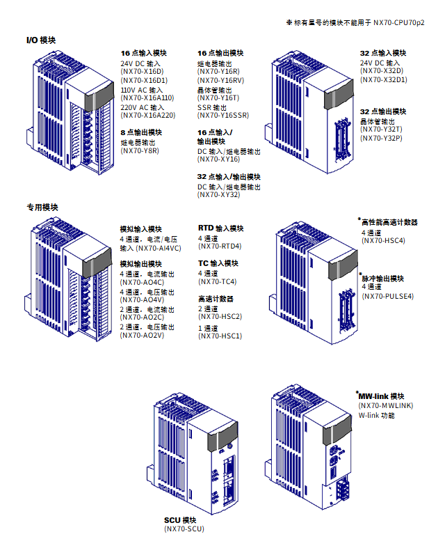
Digital I/O module
|Module Type | Model Example | Points | Core Parameters|
|DC input | NX70-X16D | 16 points | 12-24V DC, response time ≤ 2ms|
|AC input | NX70-X16A220 | 16 points | 200~240V AC, input impedance 20K Ω|
|Relay output | NX70-Y16R | 16 points | 250V AC/30V DC, 1A/point|
|Transistor output | NX70-Y32T | 32 points | 12~24V DC, 0.4A/point (NPN type)|
|SSR output | NX70-Y16SSR | 16 points | 100~240V AC, 0.5A/point|
Simulation and specialized modules
|Module type | Model | Number of channels | Core specifications|
|Analog Input (AI) | NX70-AI4CV | 4-channel | Voltage ± 5/± 10/0~10V, Current 4~20mA, 16 bit resolution|
|Analog Output (AO) | NX70-AO4C | 4-channel | Current 4-20mA, 14 bit resolution, conversion speed 2.5ms/channel|
|RTD Input | NX70-RTD4 | 4-channel | Supports Pt100/Pt1000/Ni100, Resolution 0.1 ℃|
|High speed counter | NX70-HSC4 | 4-channel | 200kcp, 32-bit up and down counting|
|Communication module | NX70-SCU | 2-port | RS232/RS485, supports ASCII/binary communication|
Software Programming and Addressing System
(1) Programming tools and instruction sets
Programming tool: WinGPC (Windows system, V3.5 and above), supporting program editing, downloading/uploading, I/O monitoring, and timing diagram analysis;
Programming method: Supports IL (Instruction List) and FUPLA (Function Block), requiring the use of a dedicated communication cable (NX_CBLCPU2/5) for connection;
Instruction set: There are a total of 175 instructions, including 28 basic sequential instructions (STR/AND/OR, etc.), timer/counter instructions (TIM/UC/DC, etc.), arithmetic/logic instructions (ADD/MUL/WEND, etc.), and program control instructions (JMP/CALL/INT, etc.).
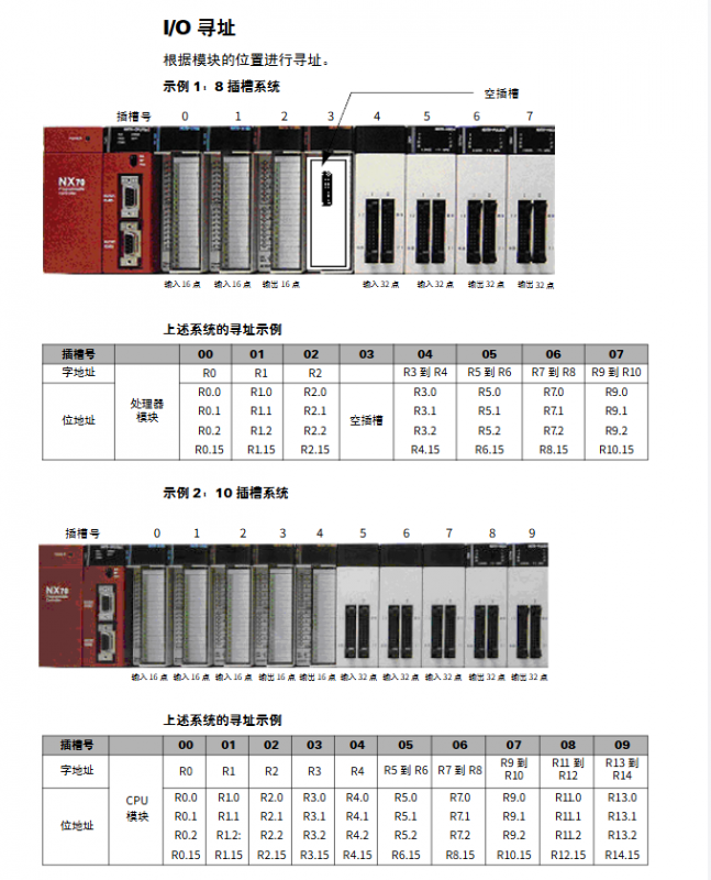
(2) Addressing method and storage area
Storage area division
|Regional identification | Function | Address range | Key characteristics|
|R (External I/O) | External I/O module mapping | R0.0~R127.15 (2048 points) | Addressing in module slot order|
|M (internal contact) | Auxiliary logic operation | M0.0~M127.15 (2048 points) | Power off reset|
|K (hold contact) | Power off hold logic | K0.0~K127.15 (2048 points) | Retain state after power off|
|W (data register) | stores numerical data | W0000~W2047 (expandable to 4096 words) | supports word/double word operations|
|TC (Timer/Counter) | Timing and Counting | TC000~TC255 (256 channels) | Set Value SV (W2048~W2303), Current Value PV (W2304~W2559)|
addressing mode
Bit addressing: used for contact states (such as M0.5, R1.3), representing a single switch state (0/1);
Word addressing: used for numerical storage (such as W0010), 16 bits, storage range 0~65535;
Double word addressing: composed of two consecutive words (such as W0010+W0011), 32-bit, with a storage range of 0~4294967295;
Absolute addressing: indirectly accessing registers through decimal/hexadecimal absolute addresses (such as R0 corresponding to absolute address 0000H).
Installation, wiring, and maintenance
(1) Installation requirements
Environmental conditions: working temperature of 0-55 ℃, humidity of 30% -85% (no condensation), avoiding direct sunlight and strong electromagnetic interference (with a distance of ≥ 100mm from high-voltage equipment);
Installation method: 35mm DIN rail installation, modules are installed in the order of “power supply → processor → I/O/dedicated module”, with reserved heat dissipation space (≥ 55mm above, ≥ 75mm below);
Grounding requirements: separate three-phase grounding, grounding wire ≥ 2mm ², grounding resistance ≤ 100 Ω.
(2) Wiring specifications
Power wiring: The AC input module needs to distinguish between 110V/220V specifications, and 24V power supply cannot be connected in parallel with external commercial power supply;
Input wiring: The DC input module supports NPN/PNP sensors, and dual line sensors require parallel leakage resistors to avoid false triggering;
Output wiring: Inductive loads require parallel protection circuits (diodes/variable resistors), and the relay outputs a maximum load of 3A/point;
Communication wiring: RS485 communication requires a terminal resistor (DIP switch connected to the endpoint station), with a maximum transmission distance of 1.2km.
(3) Maintenance and troubleshooting
Regular inspection: Check the power supply voltage, wiring tightness, and module status LED every 6 months;
Common troubleshooting:
|Fault phenomenon | Possible cause | Handling method|
|Power LED not lit | Fuse blown | Replace 250V 1A fuse|
|Output cannot be connected | Load short circuit/loose wiring | Check the load and terminal screws|
|Input unresponsive | Sensor power failure/excessive leakage current | Check sensor power supply, parallel leakage resistor|
|Communication failure | Baud rate mismatch/wiring error | Check DIP switch settings and TXD/RXD wiring|
Battery maintenance: The CPU module is equipped with a CR2032 battery, which has a lifespan of 3 years in a 25 ℃ environment. When the battery is low, the BATT LED lights up and needs to be replaced in a timely manner.
Product catalog and dimensions
Core Product Catalog (Key Models)
|Product Category | Model Example | Core Specifications|
|Processor | NX70-CP70p2 | 20k steps, 2 communication ports RTC |
|Base plate | NX70-BASE12 | 12 slots, supporting 384 I/O points|
|Power Supply | NX70-POWER1 | 110~220V AC Input, 5V/4A+24V/0.3A|
|Digital input | NX70-X32D1 | 32 point 24V DC input, connector type|
|Digital output | NX70-Y32P | 32 point PNP transistor output, 0.4A/point|
|Simulation module | NX70-RTD4 | 4-channel RTD input, supporting Pt1000|
Key dimensions (base plate)
|Base plate model | Number of slots | Length A (mm) | Width B (mm)|
| NX70-BASE02 | 2 | 149.5 | 129.5 |
| NX70-BASE06 | 6 | 291.5 | 271.5 |
| NX70-BASE12 | 12 | 433.5 | 413.5 |