Parker Compumotor ZETA6000 series single axis independent drive controller
Introduction
In modern industrial automation, single‑axis motion subsystems demand compactness, ease of installation, high positioning accuracy, low vibration, and reliable long‑term operation. Traditional motion setups often separate drive and controller components, increasing wiring complexity, installation time, and potential points of failure. The Parker Compumotor ZETA6000 Series addresses these challenges with an all‑in‑one drive/controller design that consolidates motion computation, power drive, signal conditioning, and I/O management into one unit. Built on the proven 6000 Series command platform, the ZETA6000 Series maintains programming simplicity while supporting advanced functions such as phase shifting, electronic gearbox, and flying cutoff. It supports daisy‑chain and multi‑drop communication for multi‑axis coordination and is compatible with standard Windows‑based development tools, enabling rapid project deployment for OEMs, system integrators, and end users. This article systematically reviews the product positioning, model differentiation, performance features, interface design, software ecosystem, and environmental specifications of the ZETA6000 Series to provide a full technical reference for precision motion control applications.
Product Overview and Model Classification
The ZETA6000 Series is a family of stand‑alone, single‑axis integrated drive/controller systems engineered for cost‑effective, clean, and complete single‑axis motion solutions. The series includes four models distinguished by output current and input voltage range, allowing users to match drive capacity to motor and load requirements.
2.1 Model Lineup
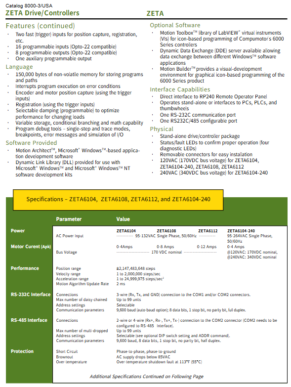
ZETA6104: 4 Apk motor current, 95–132 VAC single‑phase input, 170 VDC nominal bus voltage.
ZETA6104‑240: 4 Apk motor current, wide‑range 95–264 VAC single‑phase input, supporting 120 VAC (170 VDC) and 240 VAC (340 VDC) operation.
ZETA6108: 8 Apk motor current, 95–132 VAC single‑phase input, 170 VDC nominal bus voltage.
ZETA6112: 12 Apk motor current, 95–132 VAC single‑phase input, 170 VDC nominal bus voltage.
All models share the same control core, command set, I/O structure, and communication protocol, ensuring interchangeability and simplified inventory management. The series uses removable screw terminals and a standard 50‑pin header, eliminating connector cutting or rework during cable routing and significantly reducing on‑site installation and maintenance time.
2.2 Scalability for Multi‑Axis Systems
Although designed primarily for single‑axis use, the ZETA6000 Series supports scalable multi‑axis coordination:
Up to 99 units can be daisy‑chained via RS‑232C.
Up to 99 units can be multi‑dropped using RS‑485 (with 32 units recommended for standard multi‑drop topology).
This architecture enables modular expansion in assembly lines, indexing tables, winding machines, and cut‑to‑length systems without dedicated multi‑axis controllers.
Core Motion Performance and Proprietary Technologies
The ZETA6000 Series achieves industry‑leading smoothness and responsiveness through dedicated motion control algorithms and proprietary damping technologies, setting it apart from conventional stepping systems.
3.1 Performance Specifications
Position range: ±2,147,483,648 steps, supporting high‑precision long‑travel positioning.
Velocity range: 1 to 2,000,000 steps per second, covering low‑speed smooth scanning and high‑speed traversing.
Acceleration range: 1 to 24,999,975 steps/sec², supporting fast start‑stop and high‑dynamic maneuvers.
Motion algorithm update rate: 2 ms, ensuring real‑time responsiveness and trajectory stability.
Encoder input: Differential or single‑ended incremental encoder support, TTL/CMOS compatible, maximum input frequency 1.6 MHz, minimum transition interval 625 ns.
3.2 Active Damping™ Technology
Active Damping™ improves dynamic stiffness and stability in stepper motor systems:
Achieves damping ratios up to 0.5.
Increases acceleration compared to conventional step systems.
Reduces mid‑speed resonance and motor vibration.
Boosts effective shaft power and continuous throughput.
Enhances overall contouring and positioning stability.
3.3 Electronic Viscosity™ Technology
Electronic Viscosity™ optimizes steady‑state and low‑speed behavior:
Reduces settling time for high‑precision positioning tasks.
Improves smoothness at slow speeds and minimizes velocity ripple.
Lowers audible noise during operation.
Together, these two technologies make the ZETA6000 Series suitable for semiconductor equipment, laboratory automation, packaging, and labeling machinery.
Electrical Specifications and Power Design
The ZETA6000 Series uses a regulated DC bus architecture to deliver clean, stable power to stepping motors while maintaining compatibility with global mains supplies.
4.1 Input Power and Bus Voltage
ZETA6104, ZETA6108, ZETA6112: 95–132 VAC single‑phase, 50/60 Hz, nominal 170 VDC bus.
ZETA6104‑240: 95–264 VAC single‑phase, 50/60 Hz; 170 VDC at 120 VAC, 340 VDC at 240 VAC.
Wide‑range operation supports deployment in regions with unstable or varying grid voltage.
4.2 Motor Output Current
ZETA6104 / ZETA6104‑240: 0–4 Apk.
ZETA6108: 0–8 Apk.
ZETA6112: 0–12 Apk.
The current range supports small‑to‑medium frame stepper motors commonly used in labeling, cutting, positioning, and conveying applications.
4.3 Internal Power Resources
Built‑in +5 VDC supply available on COM2, encoder, and I/O connectors.
Total +5 V load current limited to 0.5 A across all I/O connections.
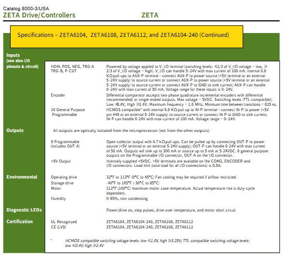
V_I/O terminal supports 5–24 V, up to 100 mA, for flexible input logic configuration.
AUX‑P and IN‑P support 0–24 V, up to 50 mA and 100 mA respectively, for sourcing or sinking I/O configurations.
I/O Configuration and Interface Capabilities
The ZETA6000 Series provides rich, optically isolated, field‑compatible I/O for direct integration with sensors, actuators, PLCs, and operator panels.
5.1 Input Interface
Home and limit inputs: HOME, POS, NEG for homing and overtravel protection.
Fast trigger inputs: TRG‑A, TRG‑B for high‑speed position capture, registration, and cut control.
16 programmable general‑purpose inputs: Opto‑22 compatible, HCMOS logic, internal 6.8 kΩ pull‑up to IN‑P.
Input thresholds: ≤1/3 V_I/O = LOW, ≥2/3 V_I/O = HIGH; 0–24 V range.
5.2 Output Interface
8 programmable general‑purpose outputs: optically isolated from the MCU, open‑collector with 4.7 kΩ pull‑up.
1 auxiliary programmable output (OUT‑A): total 9 configurable outputs.
OUT‑P supports 0–24 V, up to 50 mA; outputs sink up to 300 mA or source up to 5 mA.
Isolation improves noise immunity in industrial environments.
5.3 Communication Ports
RS‑232C port: 3‑wire (Rx, Tx, GND), 9600 baud (auto‑baud option), 8N1, full duplex.
RS‑232C/RS‑485 configurable port: supports 2‑wire or 4‑wire RS‑485, 9600 baud, 8N1, half duplex.
Unit addresses are software or DIP‑switch selectable for network identification.
5.4 Operator Interface
Direct connection to RP240 remote operator panel.
Stand‑alone operation or host control via PC, PLC, or thumbwheels.
Four diagnostic LEDs: power on, step pulses, over‑temperature, motor short circuit.
Programming Language and Software Ecosystem
The ZETA6000 Series uses the mature 6000 Series command language, balancing power and ease of use.
6.1 Command Language Features
150,000 bytes of non‑volatile memory for program and path storage.
Error interrupt handling for safe automated recovery.
Position capture and registration via trigger inputs.
Programmable damping for load adaptation.
Variable storage, conditional branching, and arithmetic functions.
Debug tools: single‑step, trace, breakpoints, error messages, I/O simulation.
6.2 Standard and Optional Software
Motion Architect™: standard Windows‑based development environment for fast program creation.
DLL library: supports Windows and Windows NT SDK integration.
Motion Toolbox™: LabVIEW virtual instruments for graphical programming.
DDE6000 Server: enables data exchange between Windows applications.
Motion Builder™: visual icon‑based development environment.
This software stack supports both script‑based and graphical programming styles.
Protection Circuits and Reliability Design
Reliability is reinforced by multi‑level protection to guard the drive, motor, and machine.
7.1 Protection Functions
Motor short‑circuit: phase‑to‑phase and phase‑to‑ground detection.
Over‑temperature: internal drive and power supply shutdown at 55°C (113°F).
Overvoltage: protects against regenerative voltage spikes.
Power dump: dissipates excess regenerative voltage.
Brownout: detects AC input below 85 VAC.
7.2 Environmental Ratings
Operating temperature: 0°C to 45°C (32°F to 113°F); fan cooling recommended for low airflow.
Storage temperature: ‑30°C to 85°C (‑40°F to 185°F).
Humidity: 0–95% non‑condensing.
Motor case temperature: maximum 100°C (212°F), dependent on duty cycle.
7.3 Certifications
UL Recognized.
CE (LVD) compliance.
These certifications support global installation and factory acceptance.
Application Scenarios and Technical Advantages
The ZETA6000 Series is optimized for single‑axis motion tasks requiring precision, quiet operation, and quick setup.
8.1 Typical Applications
Packaging and flying cutoff systems.
Labeling, printing, and registration control.
Automated positioning and indexing tables.
Winding, spooling, and material feed.
Assembly automation and pick‑place mechanisms.
Laboratory and medical instrumentation.
8.2 Core Competitive Advantages
All‑in‑one design: reduces cabinet space, wiring, and failure points.
Proprietary damping: low vibration, low noise, fast settling.
Flexible I/O: direct sensor and actuator connection.
Scalable networking: up to 99 axes for modular expansion.
Familiar software: short learning curve for rapid deployment.
Global power compatibility: supports worldwide facilities.
Industrial protection: stable operation in harsh environments.