OMRON Machine Automation Controller NX-series System Units
The OMRON NX series system unit (power/shielding/connection unit) user manual (W523-E1-10) is designed for four types of modules: NX-PD/PF/PC/TBX. It provides detailed information on system composition, specifications, installation and wiring, terminal usage, fault diagnosis, and maintenance. It specifies core specifications such as 24VDC power supply, spring screw free terminals, TS/UNIT PWR/I/O PWR indicator lights, 100 Ω grounding, and anti misconnection coding pins, covering three application architectures: CPU rack, slave terminal, and secure network controller. It is an authoritative guide for NX series power expansion and wiring.
Module core specifications
General Specifications
Parameter indicators
Working temperature 0~55 ℃
Humidity 10~95% RH (no condensation)
Grounding ≤ 100 Ω
Pollution level 2
Overvoltage category II
Insulation withstand voltage 510VAC/1min
Power module specifications
Model Function Voltage Maximum Current
NX PD1000 NX unit power supply 24VDC 10W
NX PF0630 I/O power supply 5~24VDC 4A
NX PF0730 I/O power supply 5~24VDC 10A
NX PC00xx I/O power adapter -4A/terminal
NX – TBX01 Shielded Grounding -14 Channel SHLD
System composition
CPU rack architecture
CPU unit+NX system unit+I/O unit+end cap
Slave terminal architecture
EtherCAT coupler+NX system unit+I/O unit+end cap
Security Controller Architecture
Communication control unit+security CPU+NX system unit+end cover
Installation specifications
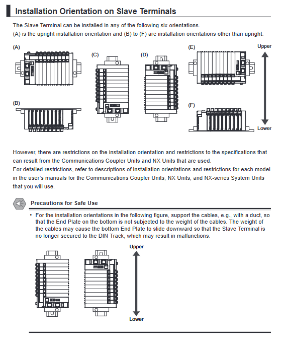
Installation method
DIN 35mm rail installation, vertical forward direction
Module splicing: alignment of guide slots, locking of yellow slider
Prohibited items
Power on disassembly and assembly, touching NX bus pins, labeling/writing restricted areas
Distance requirements
Adequate space for upper and lower heat dissipation, with cables supported by force
Core wiring specifications
1. Power supply classification
Unit Power: Provides power to the controller and modules internally
I/O Power: Provides power to sensors/actuators
Requirement: The two channels must be independently powered to avoid noise interference
2. Screw free terminal operation
Applicable wire diameter: 0.08~2.0mm ²
Plug in: directly push in; Wiring: Insert a slanted straight screwdriver (10-15 °)
High current (>2A) must use tin plated wire or cold pressed terminals
Binding: Binding at a distance of * * ≤ 30mm * * from the terminal
3. Anti misplacement coding pin
Code sales: NX-AUX02
6 hole combinations with 20 different codes to prevent incorrect terminal connections
4. Shielding grounding
NX-TBX01 provides 14 SHLD terminals, uniformly grounded to reduce interference
Functional grounding: ≤ 100 Ω, single point grounding
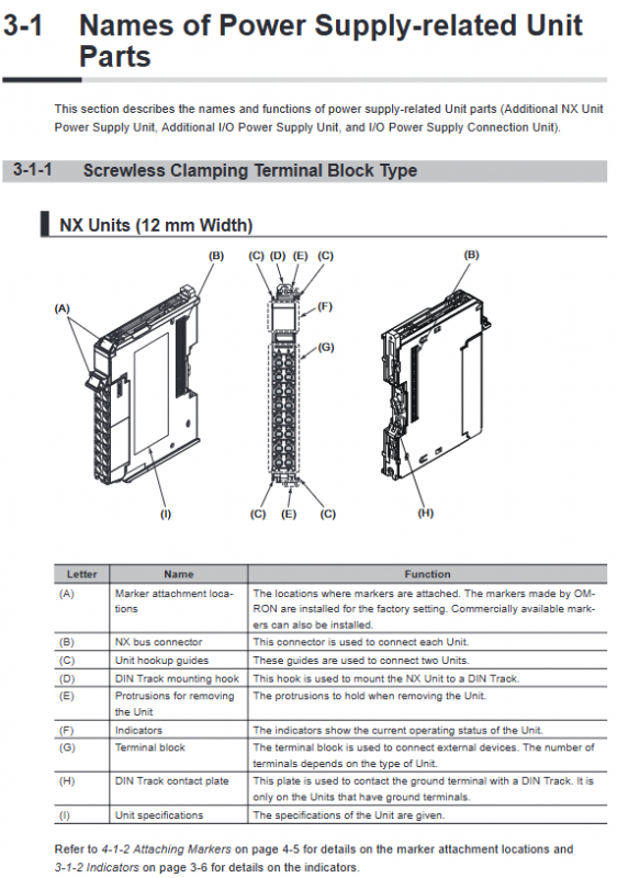
Status indication and diagnosis
LED status
Meaning of indicator light status
TS (green) is always on and running normally
TS (flashing green for 2s) initialization/download normal waiting
TS (red) constantly on, hardware failure
TS (flashing red for 1 second) bus communication abnormality check connection
UNIT PWR green NX unit power supply is normal
I/O PWR green I/O power supply is normal
Key Event Code
Event code fault handling
00200000 hex non-volatile memory hardware failure reboot/replacement unit
9040000hex event log clearing normal operation
Maintenance and Inspection
routine inspection
Indicator lights, wiring, terminals, heat dissipation
Regular inspection (6-12 months)
Voltage measurement, terminal torque, ambient temperature and humidity, grounding
clean
Wipe with a dry cloth; Dilute oil stains with 2% cleaning agent
Prohibited use: thinner, benzene, chemicals
Key issues
Question: Why must the unit power supply and I/O power supply of NX series system units be separated? What are the risks of not separating?
Answer: The unit power supply is responsible for the internal power supply of the controller and module, while the I/O power supply is responsible for the external load power supply; Separation can prevent load noise from entering the control system. Failure to separate can lead to misoperation, communication abnormalities, and module damage, which is a mandatory safety regulation.
Question: What are the mandatory requirements for wire diameter, cold pressed terminals, and binding distance when using screw free terminal wiring?
Answer: Applicable wire diameter is 0.08~2.0mm ²; If the current is greater than 2A, tin plated wire or cold pressed terminals must be used; The cable must be tied and fixed within 30mm from the terminal to prevent pulling and loosening.
Question: What on-site pain points do the four types of units NX PD/PF/PC/TBX solve? What are their respective core purposes?
answer:
PD: Solve the problem of insufficient CPU power supply and expand the NX unit power supply;
PF: Solve the problem of I/O total current exceeding the limit, expand I/O power supply and achieve partition isolation;
PC: Solve the problem of insufficient I/O power terminals and provide multiple adapter terminals;
TBX: Solve the problem of disorderly shielding and grounding of multiple cables, and unify shielding and grounding to reduce interference.