Operator Manual for AutroSafe Interactive Fire Detection System (Release 4)
Positioning and Applicable Objects
Applicable equipment: BS-420/BS-430, BC-420, BU-BV-420, BU-110, BV-110
Applicable personnel: firefighters, safety administrators, system operators, maintenance personnel
Core uses: daily operation, fire alarm disposal, fault handling, testing and maintenance, system configuration
Hardware Panel and Operation Fundamentals
1. Panel type
Panel type function
BS-420/BS-430 main operation panel, fully functional
BU-BV-420 relay panel, can be used as a fire/information panel
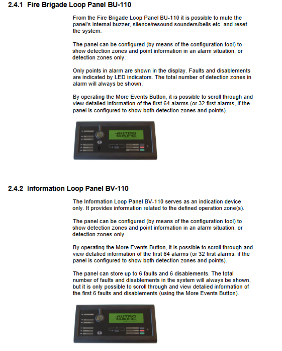
BU-110 circuit fire protection panel
BV-110 Circuit Information Panel
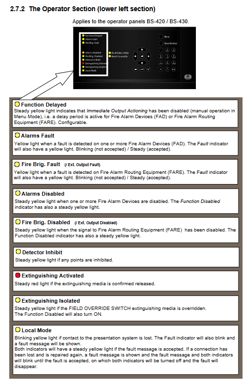
2. Core indicator light
FIRE (red): flashing=fire alarm; Always on=muted
Fault (yellow): flashing=fault not accepted; Always on=accepted
Power (green): Always on=power supply is normal
Testing (yellow): Test mode
Function Disabled (yellow): Shielding exists
Function Delayed (yellow): Output delayed activation
3. Core buttons
Mute Panel: Mute the local buzzer
Silence Alarms: Mute the sound and light of the entire field
Reset System: System reset (needs to be muted first)
Menu: Enter menu mode
More Events: Page up to view more events
Lamp Test: Lamp Inspection (Information Panel)
4. Access permission level
The level permission method can execute operations
1. No viewing, light inspection, mute
2. Key mute, reset, view details, basic shielding
3. Password configuration, maintenance, testing, upgrading, and setup
4. Special tool maintenance, hardware replacement, firmware flashing
Operation Mode
1. System status priority
Fire alarm>Warning>Fault>Shielding>Testing
2. Alarm display mode
Default: Display both region and location simultaneously
Optional: Display only in the region, press the number key 1 to view the point position
3. Type of detection area
Immediate action zone: Alarm immediately linked
Composite action area: linkage is only activated when there are at least 2 alarm points
Delay action area: T1 initial delay → T2 extended delay
Delay composite zone: divided into three levels of silence/low alarm/high alarm during the day; Immediately report to the police at night
SOLAS zone: exclusively for maritime use, capable of blocking alarms after delay
4. Core operations
Silent buzzer: Press Mute Panel
Mute sound and light: Press Silence Alarms
Restarting sound and light: Press the number key 1 (RESOUND)
System reset: Mute first, then press Reset
Accept Warning/Fault: Press the number key 4 (Accept)
View Points: Select Area → Press Number Key 1 (SHOW POINT)
Delay operations: ActiveE, PROLONG
Menu Mode
The main menu has a total of 5 items
Show Status
Fire alarm, warning, malfunction, shielding, testing, activation output, active sensors, oil and gas shielding points
Disable (shield)
Detection area, location, fire alarm equipment, alarm routing, output, carrier, immediate output action
Can set the duration of blocking, automatically recover after timeout
Enable (Unblock)
Corresponding to blocking one by one, restore all devices
System (System Settings)
Date and time, version information, level 3 permissions, password, printer, language, initialization, unblocking point, day and night timer
Service (maintenance instruction, requiring level 3 permissions)
Testing: Area testing, output testing (sound and light/routing/fire extinguishing)
Log: Fire alarm, warning, malfunction, blocking, operation, testing, all events, log settings
Circuit command: shield circuit, release circuit
Report: Self check faults, contamination probe, export SV report to USB
Upgrade: software upgrade, configuration upgrade, export configuration/logs, restart
Remote access: Web switch (automatically turned off after 12 hours)
Dual machine hot standby: main/backup system switching
Oil and gas specific: shielding points, canceling shielding, setting alarm thresholds, reading measurement values
Standard Event Handling Procedure
1. Fire alarm handling
Follow the on-site fire safety plan
Press Mute Panel to mute this device
View alarm area/location
on-site verification
Press Silence Alarms to silence
After the fire is resolved, press Reset to reset
The points that are still alarming can be disabled by Alarm Disable, and reactivated after repair
2. Delayed fire alarm handling
PROLONG (Extended Delay) or ACTIVATE (Immediate Activation)
The manual alarm button usually skips the delay and is directly linked
3. Pre alarm/Early Warning
Mute
View Region/Location
on-site verification
Accept alerts according to Accept
Reset to restore normal operation
4. Fault handling
View fault types (detector, circuit, communication, equipment)
Accept faults according to Accept
Notify maintenance personnel to carry out repairs
Reset and clear the fault after repair
Partition logic (core architecture)
Detection Zone DZ: Detector/Manual Alarm Combination, Trigger Source
Alarm Zone AZ: Sound and Light Equipment Group, triggered by the Detection Zone
Operation area OZ: Operator permission range, can be nested in multiple layers
Appendix Key Content
Action Digits: Shortcut keys for numbers (display point, beep, activate, extend, accept)
Glossary: DZ, AZ, OZ, FAD, FARE, FWRE, FPE, SOLAS, Dual Safety
Complete menu tree: Full functional hierarchical structure diagram
Key issues
Question 1: What are the operation scopes corresponding to the four levels of permissions in the AutroSafe system? What conditions must be met to reset the system?
answer:
Level 1: No permission, only view, mute, light check;
Level 2: Key permissions, mute, reset, view points, basic shielding;
Level 3: Password permissions, maintenance, testing, upgrading, configuration modification;
Level 4: Specialized tools for hardware repair and firmware replacement.
The reset must first perform Silence Alarms silencing, otherwise the reset is invalid.
Question 2: What is the delay mechanism of Delayed Action? What are the two key operations that operators can perform? Is the manual alarm button subject to delay restrictions?
answer:
Delay is divided into T1 initial delay and T2 extended delay, and the arrival time automatically activates the output.
Operator can execute: Activate immediately, PROLONG extends delay.
The manual alarm button is usually not limited by delay and can be directly linked immediately.
Question 3: What events can be recorded by the logging function in the Service menu? How to only view fire alarms for a specified date and area?
answer:
Recordable: fire alarm, warning, early warning, malfunction, blocking/lifting, user operation, testing, all events.
Set in Log Setup:
Set Read Mode to From time;
Enter the start and end date and time;
Read Filter: Select Detection Zone and specify the area;
Enter Fire Alarms to filter and view.