Pilz PZE 9 Safety Relay Expansion Module
Pilz PZE 9 is a forced guide contact expansion module used for safety circuit expansion, providing 8 safety normally open contacts and 1 auxiliary normally closed contact. It supports a wide range of 24VDC/24~230VAC power supply and meets PL e/Cat.4/SIL3 safety levels. It realizes diagnosis and fault monitoring through the feedback loop of the basic unit, and has short-circuit/open circuit/ground fault protection. It is installed on DIN rails and suitable for industrial safety emergency stop, safety door and other circuit expansion, complying with international standards such as EN ISO 13849-1.
Basic Information and Security Standards
product attributes
Model: PZE 9, Safety Relay Contact Expansion Module
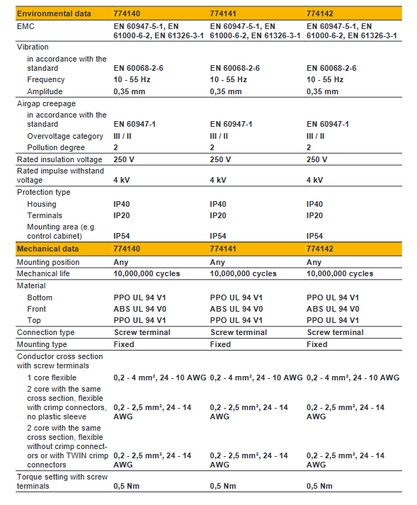
Standards: EN 60947-5-1, EN 60204-1, EN ISO 13849-1
Certification: CE, UKCA, CCC, T Ü V, cULus, EAC
Security Warning Level
DANGER: Immediate Fatal Risk
Warning: Serious Injury Risk
CAUTION: Minor injury/equipment damage
NOTICE: Equipment damage prompt
Compliant use
Contact extension for safety relays/safety systems only
Prohibition of modification and use beyond specifications
Installation and debugging must be carried out by professionals with professional qualifications
Core functions and structure
Contact configuration
Type Quantity Function
Safety contact (NO) 8-way execution safety cut-off, forced guidance
Auxiliary contact (NC) 1-channel status indication, non safety purpose
Work logic
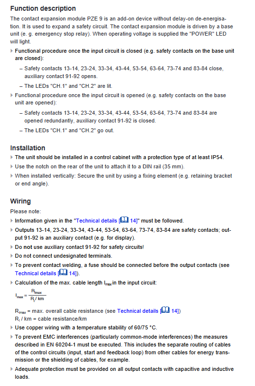
Input closed → safety contact closed, auxiliary contact disconnected, CH1/CH2 light on
Input disconnected → contact redundancy disconnected, indicator light off
Fault status → Output power loss, contact disconnection
Fault protection
Input open circuit, short circuit, ground fault
Contact adhesion prevents restart
Abnormal monitoring of feedback loop
Electrical specifications (key models)
Power supply model
Order number, power supply type, voltage, power consumption
774150 DC 24VDC 3.5W
774140 AC 24VAC 7VA
774148 AC 230VAC 7VA
output capability
Safety contacts: AC1 240V/8A, DC1 24V/8A
Auxiliary contacts: AC1 240V/2A, DC1 24V/2A
Short circuit withstand: 1kA
Contact material: AgSnO ₂+gold plating
Installation and wiring
Installation method
35mm DIN rail installation, protection level IP40 (shell)
Control cabinet protection ≥ IP54
Wiring requirements
Wire diameter: 0.2~4mm ², torque 0.5Nm
The output front-end must be equipped with a fuse (safety contact 10A fast melting)
Prohibit using auxiliary contacts for safety circuits
EMC requirements
Separate wiring of control lines and power lines
Inductive loads require the installation of arc extinguishing devices
Status indication and maintenance
LED indicator
POWER: The power supply is normal
CH.1/CH.2: Corresponding channel contact closure
Fault: Fault alarm
maintenance cycle
PL e/SIL3: Check once a month
PL d/SIL2: Check once a year
Service life: 20 years (TM)
Safety characteristic parameters
Parameter values
Performance level PL e
Category Cat. 4
SIL SIL 3
PFH D 2.31×10⁻⁹ 1/h
PFD 2.03×10⁻⁶
Mechanical lifespan of 10000000 cycles
Key issues
Question 1: What are the core security levels and corresponding inspection cycles of PZE 9?
Answer: The core security level is PL e, Cat. 4, SIL 3; The inspection cycle requires PL e/SIL3 to be conducted once a month, and PL d/SIL2 to be conducted once a year.
Question 2: What are the key differences in the use of PZE 9’s 8-way safety contacts and 1-way auxiliary contacts?
Answer: The 8-way safety contact is a forced guiding structure that can be used to safely cut off circuits; One auxiliary contact is only used for status indication and is strictly prohibited from connecting to the safety circuit.
Question 3: What faults occur in PZE 9 that prevent it from restarting, and how to handle them?
Answer: Unable to restart when there is an input short circuit/open circuit/ground fault, or when the safety contact is stuck; The handling method is to eliminate external wiring faults, confirm that the contacts have been completely disconnected, and restart the basic unit.