Pilz PNOZmulti series safety control system
Product Overview
PNOZmulti includes three series of configurable security controllers, all of which adopt a basic unit+expansion module architecture and are configured by PNOZmulti Configurator software:
PNOZmulti Classic: Standard Safety Small Controller
PNOZmulti Mini: Compact Safety Controller
PNOZmulti 2: New generation high-performance secure small controller
System Expansion Rules (Core)
1. General constraints
Only one basic unit is allowed to be used
Expansion modules can be installed on the left/right side of the base unit
The maximum expansion quantity is determined by the basic unit model
2. Maximum scalability of each series
(1)PNOZmulti Classic
Maximum number of modules for expansion position
8 expansion modules on the right side of the basic unit
4 extensions and 1 fieldbus module on the left side of the basic unit
Distributed modules (ml2p) with 4 modules per link, up to a maximum of 16 modules
(2)PNOZmulti Mini
Maximum number of modules for expansion position
One sigma expansion module on the right side of the basic unit
On the left side of the basic unit, there is 1 fieldbus, 1 communication module, and 4 link modules
Distributed modules (mml2p) with 4 modules per link, up to a maximum of 16 modules
(3)PNOZmulti 2
Basic model, maximum on the right and maximum on the left
PNOZ m B0 6 x 4 expansion+1 communication+1 bus
PNOZ m B1 12 x 4 expansion+1 bus
PNOZ m B0.1 1 with 4 extensions+1 communication+1 bus
PNOZ m C0 0 pieces 0 pieces
Supported types of extension modules
1. General modules
Input modules: secure digital input, analog input
Output modules: relay output, semiconductor output, bipolar output
Link module: Multi machine interconnection, distributed I/O link
Fieldbus modules: Profinet, EtherCAT, CANopen, Profibus, etc
Motion monitoring module: single/dual axis speed and position monitoring
Distributed module: PDP67 (IP67, 8 secure inputs)
2. Series exclusive modules
Classic: ms1p-ms4p speed monitoring module
Mini: PNOZigma Relay Expansion
2nd generation: EF series integrated input/output, SafetyNET p communication
System response time (core formula)
1. General calculation formula
Classic/Mini:
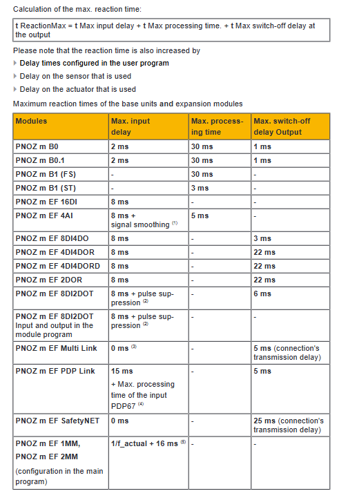
TReactionMax=maximum input delay+maximum output disconnect delay
PNOZmulti 2:
TReactionMax=maximum input delay+maximum processing time+maximum output disconnect delay
2. Typical delay parameters
Series Typical Input Delay Typical Processing Time Typical Output Delay
Classic 4ms – 30~50ms
Mini 4ms -30ms+module delay
2nd generation 2-8ms 3-30ms 1-22ms
3. Typical calculation examples
Classic: m1p input+mo4p output → 54ms
Mini: mm0.1p input+s7 output → 64ms
2nd generation: B0 input+4DI4DOR output → 54ms
2nd generation: 1MM2DO module → fastest 20ms
Multi system Interconnection Specification
1. Interconnection method
Multi Link: Interconnected through linking modules, with a maximum of 4 linking modules per basic unit
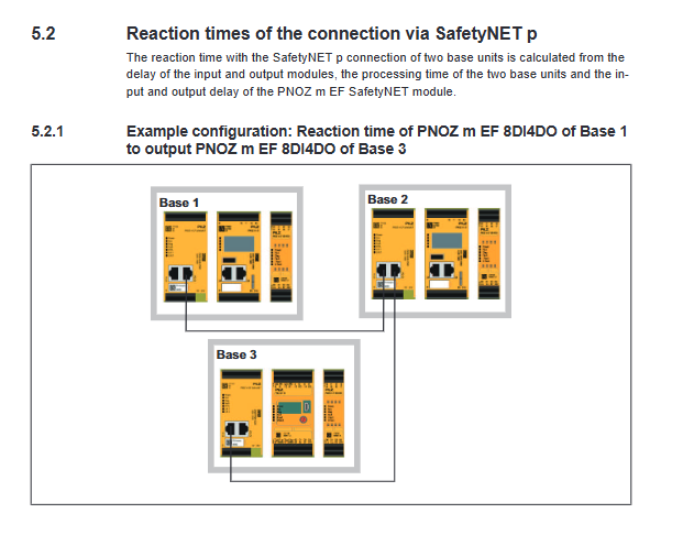
SafetyNET p RTFL: PNOZmulti 2 dedicated, linear topology up to 16 units
2. Interconnection latency
Multi Link: Add 35ms transmission delay per link
SafetyNET p: Increase transmission delay by 25ms per link
Multi machine cascading: Delay superposition (such as 3-machine interconnection → 104ms)
Key issues
Question 1: What are the core differences in reaction time calculation between PNOZmulti 2 and Classic/Mini?
Answer: Classic and Mini only require input delay and output delay; PNOZmulti 2 must add a processing time term, and the 2nd generation basic unit has a minimum input delay of 2ms and a maximum output of 1ms, making it faster and more accurate overall.
Question 2: How many distributed I/O modules can the PNOZmulti system expand up to and how can it be implemented?
Answer: Through the extension of link modules (ml2p/mml2p/EF PDP), each link module supports 4 PDP67 modules, and the entire system can support up to 16 distributed IP67 modules.
Question 3: How to calculate the response time when multiple PNOZmulti systems are interconnected? Please provide examples to illustrate.
Answer: For each additional Multi Link link, add a 35ms transmission delay. Example: Three Classic cascades → total delay=input 4ms+link 35ms+link 35ms+output 30ms=104ms.