OMRON FH/FHV series visual sensor controller
The official English user manual for Omron FH/FHV series visual sensor controllers covers all models of FH-2000/5000/L and FHV7, providing a complete explanation of system architecture, safety specifications, hardware installation, software operation, scene editing, communication configuration, advanced functions, troubleshooting, supporting up to 8 camera access, 4 operating modes, parallel high-speed processing, and multi protocol communication (EtherCAT/EtherNet/IP/PROFINET). It provides a full process development tool for scene/variable/macro/calibration/alignment to meet the high-precision visual inspection needs of industry.
Safety and proper usage standards
Safety precautions
Power supply: Only 24VDC, AC power supply is strictly prohibited to prevent electric shock/fire
Built in lithium battery: Do not disassemble, heat, burn, prevent explosion
LED light source: belongs to IEC62471 risk group 1/2, direct viewing is prohibited
Operation: Do not touch the terminals when powered on, and the casing should be heat-resistant to prevent burns
Applicable restrictions: Cannot be used in critical scenarios such as personal safety, medical, in vehicle, aerospace, etc
Environmental Requirements
Series working temperature, storage temperature, humidity
FH-2000/5000 0~45~50℃ -20~65℃ 35~85%RH
FH-L 0~55℃ -25~70℃ 10~90%RH
FHV7 0~40℃ -25~65℃ 35~85%RH
System architecture and hardware capabilities
Camera Connection: Supports up to 8 cameras and CameraLink Base/Medium configuration
Operation mode: 4 selectable options
Standard
Double Speed Multi input
Non stop adjustment
Multi line Random trigger (up to 8 lines)
Communication interface: Supports EtherCAT, EtherNet/IP, PROFINET, RS232C, parallel I/O
Extended storage: Supports USB, SD/microSD, network drives
Number of scenes: Up to 128 scenes per group, can be grouped for management (0-31 groups)
Core operating procedures
Hardware installation and wiring → Power on → Language selection
Camera debugging and image confirmation
System basic settings (startup, communication, operation mode)
Create measurement scenarios (process editing, processing unit configuration)
Testing and Measurement → Parameter Optimization
Mass production operation (scene switching, log saving)
Data backup and maintenance
Scene and measurement process
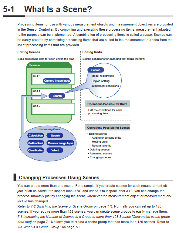
Scene: a visual detection process unit composed of multiple processing units
Typical process:
Camera image input
Filtering/compensation/positioning
Detection (search, edge, defect, color, OCR, barcode)
Judgment and output
Editing tools:
Flow Viewer: Process visualization, branch viewing
TDM Editor: Advanced Editing for Variables, Processes, and Units
System settings items
Setting Item Description
Start setting language, startup scenario, interface layout
Communication settings include serial port, Ethernet, fieldbus, and remote operation
Switching between 4 operating modes and parallel processing switch
Camera trigger delay, exposure timing, SHTOUT/STGOUT signal
Encoder triggers A/B/Z phase signals, resolution, and zeroing
Time setting system date and time, FHV needs to reset every time it is powered on
Log setting operation log, error log, image log
Advanced Features
Parallel processing: automatic/manual splitting of processes, multi-core parallelism, reducing processing time
Multi line random triggering: 1 controller independently processes up to 8 production lines
Continuous adjustment: Modify parameters online without stopping the production line
Remote operation: computer remote control, batch management, firmware upgrade
Security features: multi account permissions, operation records, and prevention of unauthorized access
Calibration and Alignment: Camera Calibration, Platform/Robot Coordinate Alignment
Maintenance and troubleshooting
Daily maintenance: clean the lens, dissipate heat and ventilation, ensure reliable grounding, and regularly backup
Fault measures:
Error code query
Operation/Error Log
NG image analysis
Retesting tool
Firmware upgrade: local/remote upgrade, supports rollback
Key questions and answers
Question 1: What scenarios are the four operating modes of FH/FHV applicable to?
answer
Standard: Universal scenario, most comprehensive functions, fastest single measurement speed
Double Speed Multi input: Ultra high beat production line, dual core alternating processing, supports the fastest trigger
Non stop adjustment: The production line cannot be stopped, and parameters and processes can be adjusted online
Multi line Random trigger: 1 control for multiple lines, capable of independently controlling up to 8 production lines, specifically designed for the FH series
Question 2: What is the measurement scene? How much can be built at most? How to break through the quantity limit?
answer
The scene is a complete visual inspection process (image input+processing+judgment+output)
Default maximum of 128 scenes per group
Breakthrough method: Use Scene Group or Scene Group Conversion tool, supporting over 128 scene management
Question 3: What is the use of parallel processing? How to open and use it?
answer
Function: Utilizing multi-core CPUs to execute detection processes in parallel, significantly reducing cycle time
Enable: System Settings → Operation Mode → Parallel Execute Set to ON
use:
Automatic Parallel: System Automatic Classification Parallel
Manual Parallel: Add Parallelize/Parallelize Task/Parallelize End Unit Custom Parallel Block