Siemens SIRIUS 3SK2 safety relay
General Principles of Basic Information and Security
Applicable products: 2 body types (22.5mm narrow type 3SK2112, 45mm wide type 3SK2122, screw terminal/spring plug terminal)+3SK26 local display+3RK35 DP bus module, can be matched with 3SK1 output expansion and 3RM1 safety motor starter; Supporting configuration software Safety ES.
Safety classification: Meets EN62061 (SIL3), EN ISO13849-1 (PL e/CAT4), and can achieve Class 0/Class 1 shutdown standards.
Warning classification: The document is divided into four levels of warnings: DANGER, Warning, CAUTION, and NOTICE. Live working must be powered off and locked, and unauthorized bypassing of safety circuits is prohibited; External independent power supply is strictly prohibited for 3SK1/3RM1, and power can only be supplied from 3SK2 through the 3ZY12 connector.
Supporting resources: Siemens Industrial Online Support, Product Selection and Configuration Tool, Security Level Assessment Tool; The DataMatrix QR code for the device casing can be quickly accessed through the official app for information.
Responsibility statement: The safety design of the entire equipment is the responsibility of the equipment manufacturer, and Siemens does not assume responsibility for the overall design of the equipment.
Product Hardware and Function Introduction
1. Hardware differences between two 3SK2 models
Project 22.5mm model 45mm model
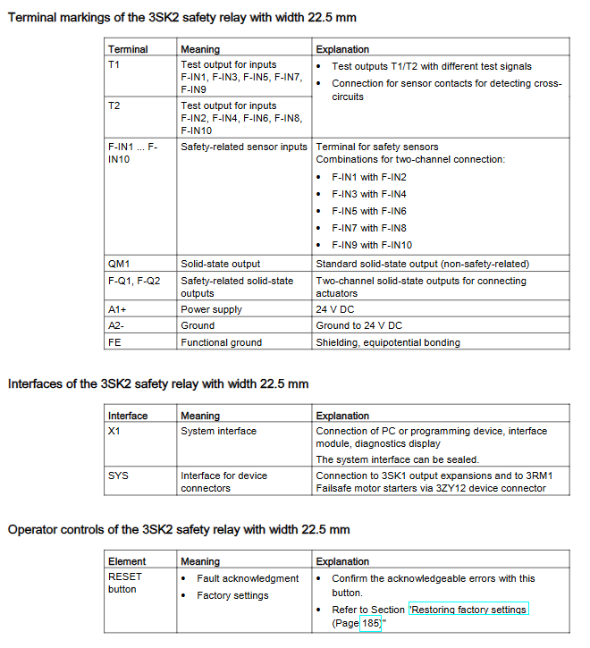
Safe input 10 points (5 sets of dual channels) 20 points (10 sets of dual channels)
Safe solid-state output with 2 channels and 4 channels
Ordinary non safety output 1 channel and 2 channels
Test power supply 1 group T1/T2 2 groups isolation T1_1/T2_1, T1_2/T2
Comes with a built-in display screen without a local button display screen
External storage without removable encrypted storage module (storage configuration)
Shared configuration: The rear SYS interface is equipped with external expansion devices through the 3ZY12 connector, with reserved system communication port X1 and panel RESET reset button (fault reset/factory reset).
2. Introduction to Supporting Accessories
3SK26 diagnostic panel: cabinet door opening installation (opening 92 × 55mm), IP54 front protection, text display fault, supports external PC, cable length up to 2.5m, can be disconnected from PC for on-site fault diagnosis.
3RK35 DP module: PROFIBUS-DP slave station, maximum speed of 12Mbps, bidirectional 32/64bit process data exchange, panel LCD can set DP address, restore factory, realize data exchange between upper PLC and safety relay.
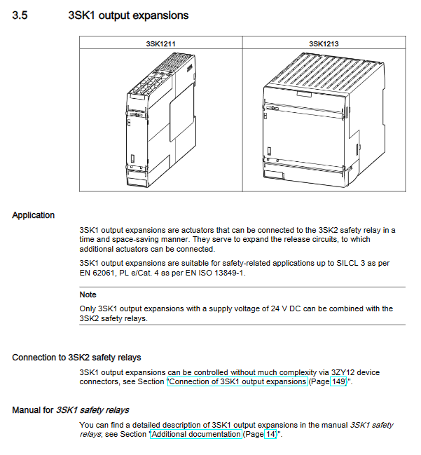
3SK1 output expansion: divided into 22.5mm (up to 5) and 90mm (only 1 and at the end), with two secure outputs bound to the main body through dialing, used for high-capacity load expansion.
3RM1 safety motor starter: direct start/forward/reverse model, with built-in fault monitoring on the body, controlled through a connector, used for motor safety cut-off.
3. Built in logic function library (Safety ES software configuration)
Monitoring functions: emergency stop, safety door, safety carpet, two handed operation (IIIc level), grating ESPE, mode switch, door with lock, etc;
Logic components: AND/OR/XOR/NOR, SR flip-flop, counter, various delays (power on/off delay);
Startup mode: automatic startup, manual startup, monitored startup (emergency stop must use controlled startup to meet PLe);
Industry standard safety features such as muting, timing monitoring, discontinuity channel deviation detection, and circuit cross short circuit detection.
4. Definition of Key Safety Terms
Dual channel redundancy: essential for achieving PL e, with no loss of safety function at a single point of failure;
Cross circuit detection: Using a variable frequency test power supply, detect cable short circuits, broken skin parallel connections, and can be turned off as needed;
Light/Dark Test: Output periodic short-term on/off self-test to determine output short circuit/open circuit. It can be turned off during delayed output, which will reduce diagnostic coverage;
Shutdown category: Cat0 immediate power-off shutdown, Cat1 delayed controlled shutdown.
Installation specifications
Installation methods: DIN35 rail buckle installation and flat screw fixation; 3SK1213、 The diagnostic panel and DP module have installation tilt angle restrictions.
System layout rules (from left to right): Diagnostic panel → DP module → 3SK2 body → 3SK1/3RM extension (up to 5, 90mm 3SK1 must be placed at the far right end of the entire string), with terminal connectors at the end.
Environmental parameters: altitude ≤ 2000m; ambient temperature varies with configuration and output power, with a maximum temperature of 60 ℃ for a single machine and 40 ℃ for multiple devices with DP/full load, requiring reserved heat dissipation gaps.
3ZY12 connector: the core component of the whole machine interconnection, divided into direct and terminal types. The 3SK1 on the terminal has a dial code, and the 3RM has no dial code.
Wiring specifications
Power supply requirements: The whole machine is powered by DC24V SELV/PELV safety ultra-low voltage, and the sensors and DP modules are supplied with the same power supply. All FE functional grounding terminals are short circuited and shielded in accordance with the specifications.
Terminal type: screw terminal (torque 0.6~0.8Nm), spring plug terminal; Distinguish the appropriate wire diameter for single/multi strand cables, and clarify the wiring requirements for different wire specifications.
Safe input wiring
Connect the dual channel sensor to the corresponding T1/T2 test power supply, enable cross short circuit detection, and meet SIL3/PLE requirements;
Passive electronic sensors (gratings, etc.) cannot be connected to the test power supply and cross line detection needs to be turned off.
Safe output wiring: Single channel wiring requires cable protection inside the cabinet to avoid short circuits, and high safety levels must have dual channel separate wiring; Inductive loads require parallel absorption circuits to prevent surge damage to the output.
Wiring of external components: 3SK1 and 3RM can only obtain electrical control signals through the SYS connector on the back. External power supply for A1/A2 is prohibited, otherwise the safety circuit will fail.
Communication wiring: The DP bus follows the PROFIBUS specification, and the terminal resistors at the beginning and end are turned on as needed. Dust plugs must be installed when the system interface is idle.
Equipment operation
3SK body: narrow type with only RESET key; Wide multiple SET/MODE buttons, used for browsing menus and viewing status on the local display screen.
3SK26 panel: Up, down, left, right+soft buttons, can switch between faults, system parameters, display settings (language/contrast/backlight duration).
DP module: SET+MODE button, menu can modify DP address (1-126), restore to factory; Lockable address modification permissions to prevent tampering.
Three operating modes
Configuration mode (yellow light): No valid program, Safety ES configuration can be downloaded;
Test mode (green light flashing): PC online forced positioning, debugging, on-site isolation of equipment to prevent misoperation;
Safe operation (constant green light): Formal production, all safety logic takes effect.
System Planning and Configuration Design
Hardware quantity limit: A single system can only have one 3SK2, with a total of ≤ 5 expansion components (3SK1+3RM).
Key points of Safety ES configuration: graphical drag and drop programming, capable of logic verification, program download, online monitoring, and supporting output forced debugging; The program cycle can be set to 10~60ms, with a fixed DP of 15ms.
Response time calculation formula: distinguish between three types of calculation formulas: normal response, single channel fault response, and dual channel fault, including sensor, input sampling, cycle, timer, output, and actuator delay. It is used for equipment safety distance calculation during selection.
Output light dark test parameter configuration: The regular output dark test is fixed at 3ms, and the delay output can be adjusted from 3 to 400ms. The parameters directly affect the fault response time and the upper limit of capacitive load.
Sensor/actuator selection: The shortest conduction time of the sensor is ≥ 2 times the program cycle; The action time of contactors and other actuators should be greater than the light test pulse to avoid misoperation.
DP configuration: Import GSD files into STEP7, which can be set with read and write permissions and password locking to prevent unauthorized rewriting of security programs by the upper level; After the bus is disconnected, the safety relay automatically uses a substitute value of 0 to maintain a safe state.
Maintenance and replacement of spare parts
Factory restoration: Power off and press RESET to power on, operate according to the indicator light sequence, clear internal configuration, and restore DP address to 126; The 45mm model synchronously clears the storage module.
Spare parts replacement: power off the entire circuit before replacement; The 22.5mm model should be backed up with software in advance, and the 45mm model should be configured by directly unplugging the storage module for reuse; After the replacement is completed, the entire system wiring and configuration will be tested item by item for functionality.
Regular annual inspection: SIL3 circuit contactor actuator components are subject to mandatory shutdown testing every year, while SIL2 undergoes differentiated testing as needed every year/month.
Multi level fault diagnosis scheme (5 diagnostic approaches)
Body LED diagnosis: Device (running), SF (group fault), BF (bus fault) three color lights, different flashes represent equipment faults, logic errors, and wiring abnormalities.
The 45mm model comes with a built-in screen: divided into input, output, and fault menus, with a single point display of 0/1/fault status.
External 3SK26 text panel: Layered menu (Fault/Status/System Configuration/Display Settings), allowing you to view specific point fault types (such as cross line, contact adhesion, startup abnormality, etc.).
PC+Safety ES: Online real-time monitoring, fault logs with timestamps.
PROFIBUS bus diagnosis: PLC reads fault codes from the DS0/DS1/DS92 dataset, and the manual defines various fault numbers and disposal plans, including hardware, configuration, bus, and wiring faults.
Key technical parameters
Safety indicators: SIL3, PLe/CAT4, SFF=99%, DCavg=99%, T1 service life of 20 years;
Electrical: DC24V power supply, safe output single channel maximum 4A, environment -25 ℃~+60 ℃;
Mechanical: DIN rail installation, protection IP20;
Wire diameter: screw terminal 0.5~2.5mm ², spring terminal 0.5~1.5mm ².
Drawings and accessories
Including product dimensions, opening drawings, and internal schematics; List the complete range of spare parts, connector models, and terminal accessories.
Application examples (core practical content of the manual)
The manual includes dozens of classic industrial safety wiring cases, covering:
Safe input: emergency stop of different levels (SIL1~SIL3), safety door (mechanical/electronic switch), 2/4 type safety light barrier, safety carpet, manual operation;
Safe output: contactor Cat0/Cat1 cut-off, 3SK1 extended drive, 3RM motor safe shutdown, frequency converter safe control;
Complex working conditions: Shielding Muting, Keyed Safety Doors, Multiple 3SK Cascades, Single/Dual Channel Hybrid Solution, covering mainstream safety design scenarios for machine tools and automated assembly lines.