KEYENCE GC-1000/GC-1000R Safety Controller
The original factory manual for KEYENCE GC series programmable safety controller is divided into two types: GC-1000 (transistor safety output) and GC-1000R (relay safety output), which meet the highest industrial safety level of SIL3/PL e/Cat.4. It relies on GC Configurator software graphical programming to adapt to safety control of emergency stop, safety door, grating, hands, shielding (Muting), PSDI press safety and other full scene equipment. The document explains safety specifications, hardware parameters, installation wiring, functional blocks, debugging and maintenance, and compliance certification from multiple dimensions.
General Provisions and Safety Management Standards
1. Warning grading
The document is divided into three types of warnings: DANGER (fatal danger), Warning (serious injury hazard), and NOTICE (equipment damage). The entire machine is only for routine industrial equipment safety control and is strictly prohibited from being used in rail transit, aviation, nuclear power, medical, and explosion-proof hazardous areas.
2. Statutory responsibilities of the safety manager
The person in charge of equipment safety shall complete the entire process in accordance with ISO13849 and ISO12100: risk assessment → defining safety functions → software program verification → overall functional acceptance of the machine, and overall safety testing before startup; After modifying the program/hardware, retesting is necessary; When the non safety PLC signal is linked to the safety circuit, the programming is forced to limit that the non safety signal can only start the safety output after the safety circuit meets the conduction conditions, to prevent false starting.
3. Definition of Product Safety Status
GC safety default fault state: all safety inputs OFF, safety outputs S-OFF disconnected; Only devices that automatically cut off output due to faults (emergency stop, Class 4 grating, safety door switch) can be connected, and the backend load must be powered off and shut down.
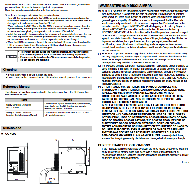
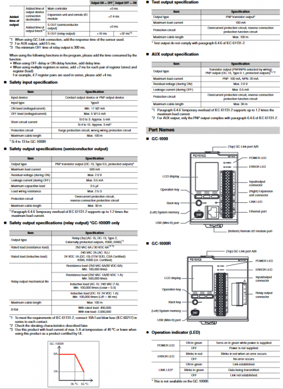
Differentiation of hardware specifications between two products
Project GC-1000 GC-1000R
Body size 60 × 95 × 90mm 85 × 95 × 90mm Weight approximately 260g approximately 360g
Safe input Si 16 points (PNP type, only supports contact/PNP sensors, NPN direct connection prohibited) 16 points
Safe output 4-channel PNP semiconductor S-OUT 3-channel normally open relay SRo+4-channel semiconductor S-OUT
Auxiliary AUX outputs 4 non safety transistor outputs 4 AUX outputs
Test output To 4 channels (for dual channel short circuit diagnosis) 4 channels
Expansion capability up to 10 expansion modules+4 remote IO units that cannot be externally connected
Communication interface 2 x GC Link, USB, Ethernet (Modbus/TCP, EtherNet/IP, PROFINET)
Power supply DC24V (± 20%) Class2 power supply, overall power consumption ≤ 200mA
Electrical parameters
Safe input: ON ≥ 11V, OFF ≤ 5V, cable length up to 100m, built-in short circuit self-test;
Semiconductor S-OUT: PNP output 500mA, load ≤ 0.5 μ F, output ≤ 30m;
GC-1000R relay output: resistive 250VAC/6A, inductive AC15 2A/DC13 1A, requiring 10A fast melting in series at the front end, with a maximum cable length of 100m;
PFHD hazard failure probability: single channel S-OUT self diagnosis opening ≈ 4.01 × 10 ⁻⁹/h, dual channel ≈ 1.01 × 10 ⁻⁹, service life of 20 years.
environmental conditions
Working temperature -10~+55 ℃, storage and transportation -25~+70 ℃, humidity 5~85%, no condensation; Altitude ≤ 2000m, pollution level 2; The whole machine needs to be installed in a control cabinet with an IP54 rating or higher, and installed on DIN35 guide rails.
Installation and wiring specifications
Cabinet installation: A heat dissipation gap of ≥ 30mm is reserved around the entire machine, and the distance between multiple module stacks is ≥ 60mm. The DIN rail is reliably grounded;
Cable specifications: Terminal adaptation 0.2~1.5mm ² (AWG16~26), relay terminal 0.2~2.5mm, wire temperature resistance ≥ 80 ℃, wire stripping 10mm;
Rigid wiring requirements
The safety output load must be connected to the 0V side, and it is forbidden to connect to+24V, otherwise the logic reversal may cause false startup;
When implementing PL e/SIL3 in a single channel, the output cable needs to be protected to avoid power line short circuits;
Inductive load parallel absorption circuit, prohibit large capacity capacitive absorbers;
Four types of OSSD grating dual channel access are required to achieve dual channel short-circuit protection and meet PLd/e.
Bus configuration: Ethernet uses Category 5e shielded twisted pair cables, GC Link comes with dedicated cables, and remote IO can be wired up to 120m away.
Software Function Blocks and Application Rules (Core Programming Unit)
Relying on the GC Configurator software for drag and drop programming, it has built-in standardized security function blocks, all of which comply with ISO and IEC security standards:
1. Reset function (manual/dual reset/presence detection reset)
Standard reset: The reset button must be installed outside the danger zone and in a visible position. Pulse input is recommended, and there is a risk of false reset due to noise from edge input;
Double reset: There are two buttons, and the last person to leave operates the second reset;
Existence of reset: Equipped with safety carpet/grating signals for reset interlocking.
2. Various Muting shielding functions (sequence/parallel/crossover/position shielding)
Sequence masking is the most commonly used, requiring 2-4 independent safety sensors to trigger masking, and PLC software signals are prohibited from triggering masking;
Parallel/Cross Shielding: Two shielded sensor cables are divided into cable trays, different shielded wires, or one open and one closed contact to prevent accidental shielding due to short circuits in the defense cable;
Shielding indicator lights should be selected according to regulations, and mechanical protection must be added for overtime shielding to prevent personnel from entering the danger zone by mistake;
Overpass: It must be operated with handheld jog control, and the hazardous area can be seen on site. An emergency stop switch should be installed nearby.
3. Manual mode MMC, bypass, door unlock, PSDI stamping dedicated
Manual mode: Three point enable/jog switch is required, automatic start is prohibited, and emergency stop remains valid throughout the entire process. It is recommended to switch modes with the key knob;
Bypass: Only for the shortest necessary duration, the bypass signal must meet the corresponding safety level;
PSD press function: limited to equipment that can be stopped urgently throughout the entire process, equipped with a Type 4 grating. This function is disabled for Japanese stamping equipment;
Door interlock unlocking: The door lock can only be unlocked when the machine reaches a safe speed/torque/shutdown state.
4. Logical block: AND/OR/NOT
Use with caution when reversing NOT, input disconnection can cause the output to be normally open and prone to accidental startup; The OR block prohibits non safety signals from opening safety circuits.
Communication and System Expansion
Ethernet: Compatible with multiple protocols, it is recommended to enable authorization codes for non secure communication reset to avoid remote false triggering of power on;
GC Link: Connect with the Keyence GS series safety door lock, read the door lock switch/locking status, and achieve door lock interlock control;
System architecture: GC-100 host+local expansion+remote IO, bus extension unit can remotely deploy IO.
Fault diagnosis, maintenance, and spare parts replacement
1. Fault classification (body LED+screen prompt)
Info minor alarm, Alert exception, Error single output cut-off, Fatal whole machine safety output tripping and shutdown.
2. Regular maintenance
First installation acceptance: full circuit wiring+full functional inspection;
Annual inspection: Full testing of the entire machine’s safety functions, and manual start stop emergency stop verification is required to cut off the self diagnostic closed circuit;
After changing lines/equipment/long-term shutdown, it is necessary to retest the safety of the entire machine.
3. Whole machine replacement
The host has a built-in system memory card, which can be replaced with a new one by unplugging and inserting the card to import the original program. After power on, the CRC check fault can be eliminated to start production.
Product Compliance Certification
Through T Ü V, UL, CSA, CE, KC and other multinational certifications, it complies with IEC61508 (SIL3), IEC62061 (SILCL3), ISO13849-1 (Cat.4/PL e), EN61131-6 safety PLC standards, and meets the European and American Machinery Directive.