Azbil SDC35/SDC36 single circuit temperature controller
SDC35 (48 × 96mm) and SDC36 (96 × 96mm) economical universal digital PID temperature control instrument technical data, using RationaLOOP+Just Fitter dual optimization PID algorithm, supporting multiple types of sensor inputs, multiple specifications of output selection, heater disconnection monitoring, remote setting, RS485 communication, modular selection, meeting various single loop temperature/pressure process controls such as heat treatment, oven, extrusion, etc.
Product appearance and installation
Panel Size
SDC35:48 (W)×96 (H); SDC36:96 (W) × 96 (H), with a machine depth of 65mm and a panel thickness of only 5mm, installed in a DIN perforated cabinet; Single or multiple units can be installed side by side, and the maximum temperature for parallel use environment can be reduced to 40 ℃ (single unit 0~50 ℃).
Weight: SDC35 ≈ 250g, SDC36 ≈ 300g; The power supply is divided into two specifications: AC85~264V wide voltage and DC24V, with a total power consumption of ≤ 12VA.
Environmental parameters: working temperature of 0-50 ℃, humidity of 10-90% RH, no condensation, in compliance with EN61010, EN61326, CE certification.
Enter hardware configuration
1. PV process input (universal)
Full specification compatibility: all types of thermocouples (K/J/R/S/B/N/T, etc.), Pt100/JPt100 thermal resistors, DC voltage (0~5/1~5/0~10V), DC current (4~20mA/0~20mA), built-in multiple division marks, and free range switching;
Sampling period of 0.1s, measurement accuracy * * ± 0.1% FS * * (thermocouple negative temperature zone ± 0.2% FS);
Equipped with wire breakage alarm: thermocouple/thermoelectric blocking wire and analog quantity exceeding the range trigger AL01~AL03 fault codes respectively.
Cold end compensation can choose between internal/external 0 ℃ compensation mode.
2. Other input terminals
1. RSP remote input: 4~20mA/0~5/10V analog signal external remote setting value; 2. DI digital input (up to 4 points): Passive contact/collector input, which can achieve functions such as manual and automatic switching, SP formula switching, self start stop, program start stop, SP slope switch, etc; 3. CT Transformer Input (2-channel optional): External 0.4~50A transformer (800 turn specification), real-time collection of heating current, heater open circuit/short circuit/half load fault detection; 4. MFB motor feedback input: adapted to valve servo motor position feedback.
Output selection (dual main control+multiple event outputs, model code differentiation)
1. Two main control outputs (optional combination: relay/pulse SSR/current/voltage)
Relay output R: 250VAC/3A resistance capacitance, mechanical life ≥ 100000 times;
2. Voltage pulse V: 19V pulse output, driving solid-state SSR, minimum conduction 1ms;
3.4~20mA current C: maximum load of 600 Ω, resolution of 1/10000, accuracy ± 0.1% FS;
4.0~5V continuous voltage D: load ≥ 1k Ω.
Support heating/cooling dual PID (cold and hot control), with one heating and one cooling output.
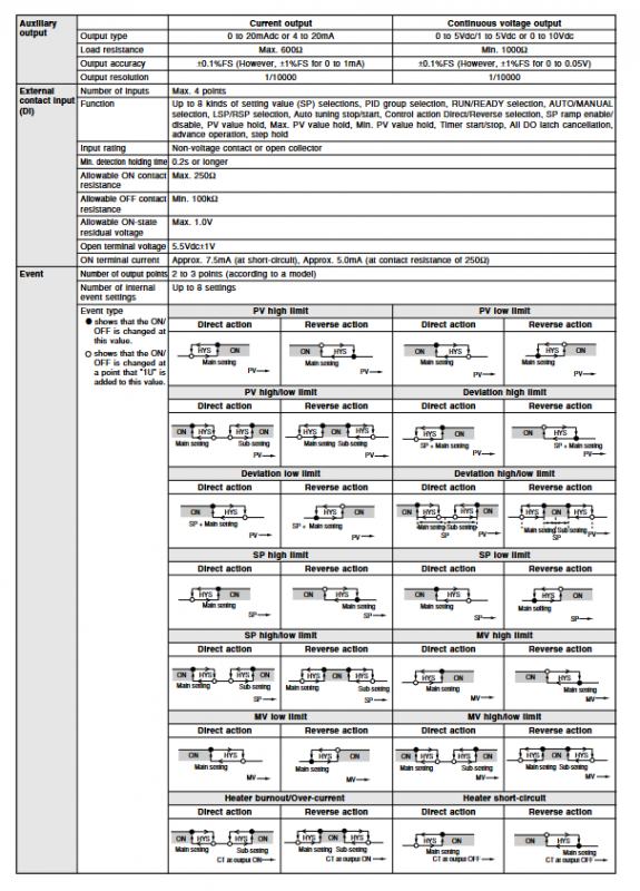
2. Event alarm output (optional 2-point/3-point relay)
Passive contact, configurable: dozens of alarm logics including PV high and low limits, deviation exceeding limits, MV output upper and lower limits, heater failure, manual and automatic, self-tuning operation, slope operation, etc.
3. Auxiliary transmission output (optional): 4~20mA/0~10V, PV/SP/MV isolated transmission.
Core control and software functions
1. PID algorithm: self-developed RationaLOOP+Just Fitter overshoot suppression algorithm, with built-in standard/fast disturbance rejection/small fluctuation PID characteristics; Supports automatic self-tuning (limit cycle method), can store 8 independent PID parameters, and can be switched with one click. 2. Control modes: ON/OFF position control, single path PID, cold and hot dual PID, valve position proportional PID. 3. Enrich logical functions
SP multi group setting (8 sets of formulas), quick switching of setting values for DI terminals;
SP lifting slope function, limiting the set value lifting rate;
Fault diagnosis of three-way circuit: detect contactor/heating tube disconnection and short circuit through CT current+output opening linkage;
Manual automatic disturbance free switching, output limiting (MV upper and lower limits).
4. Heater fault detection (CT optional): Monitor the output on/off status+load current, identify heating wire open circuit, SSR breakdown short circuit, and load phase loss.
Communication and Debugging
1. RS485 three bus (optional): Modbus type slave protocol, baud rate 4800~38400bps, up to 31 instruments can be mounted on a single bus, communication distance is 500m, and it is compatible with PLC/HMI. 2. SLP-C35 dedicated programmer: PC data cable for quick parameter download and batch configuration, eliminating the need for complex panel button settings.
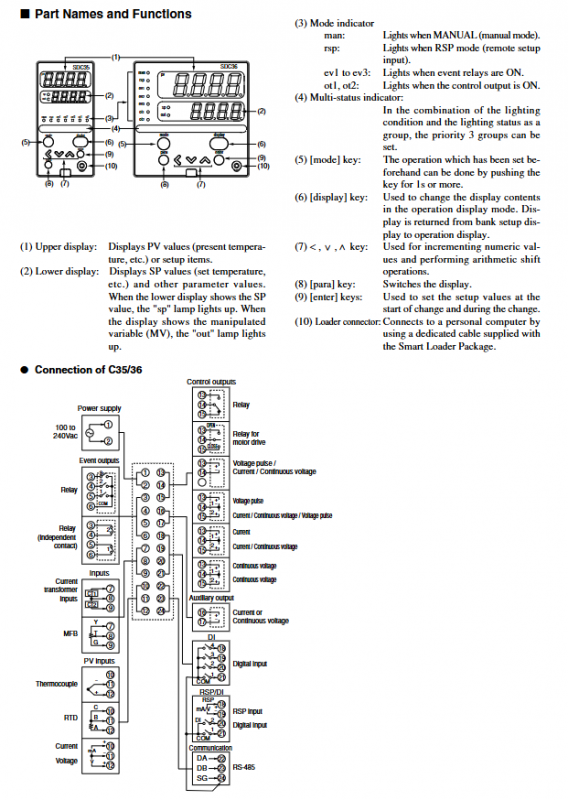
Panel operation and display
Upper and lower dual row 4-digit digits: upper green PV measurement, lower orange SP setting; Indicator lights: MAN manual/RSP remote/OT output/EV event status, coordinated with MODE, ENTER, and up and down button operations.
Model coding rules (C35TR0UA10 example)
Segmented definition: Size → Power supply → Main control output 1 → Main control output 2 → Event output → DI/CT/communication optional → Additional authentication, output, communication, DI, CT are all optional as needed.
Supporting spare parts
Install snap fasteners, terminal dust covers, two types of aperture CT current transformers (QN206/QN212), and PC programming cable SLP-C35.