OMRON NX502 model Sysmac platform machine controller hardware usage instructions
The OMRON NX502 model Sysmac platform machine controller hardware user manual focuses on the hardware parameters, system architecture, power selection, installation and wiring, troubleshooting, spare parts replacement of the NX502 full series CPU. It is equipped with Sysmac Studio software programming and debugging, product integration logic+motion control, EtherCAT master station, dual EtherNet/IP, OPC UA, database docking and other functions. The document consists of 7 main texts, appendices, terminology, and revision records.
Product Overview and Hardware Specifications
1. Product positioning
The NX502 belongs to the Ohm Sysmac mid to large integrated controller, which integrates sequential control and multi axis motion control. The main body comes with an EtherCAT master station, dual port EtherNet/IP, expandable X-Bus communication module, NX local IO module, suitable for assembly lines, machine tools, and multiple servo devices, and supports IoT upper level docking.
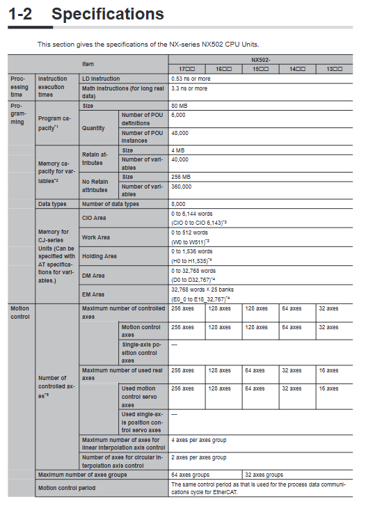
2. Hardware classification (NX502-1300~1700 five models, gradually increasing axis resources)
The program capacity is uniformly 80MB, and the variable area is 4MB for hold type and 256MB for non hold type;
Controlled real axis: 13 type 16 axis/14 type 32/15 type 64/16 type 128/17 type 256 axis;
Communication: PORT1/PORT2 dual gigabit EtherNet/IP, PORT3 100Mbps EtherCAT master station, EtherCAT can mount up to 256 slave stations;
Power supply DC 20.4~28.8V, maximum power consumption of the whole machine 18.3W, external shape 135 × 100 × 120mm, net weight ≤ 920g;
The backup clock for the main capacitor power failure is about 10 days (40 ℃), and the CJ1W-BAT01 lithium battery can be selected for long-term storage of the clock.
3. External devices of the main body
SD card slot (program/recipe/log backup), removable spring terminal, DIP configuration dip, multi status indicator light (POWER/RUN/ERR/BUSY/SD/Ethernet port light).
System hardware architecture
1. NX local rack structure
The right side of the CPU is connected to NX-BUS, with a maximum of 63 NX modules (DI/DO/analog/temperature/weighing/communication, etc.), and the rightmost end must be equipped with NX-END02 end cap; On the left is the X-BUS interface, with up to 4 X-BUS modules (typical NX-EIP201 Ethernet module). The X-BUS is directly powered by the CPU unit power supply (total output 50W), without the need for an external power supply.
2. Bus architecture
EtherCAT (PORT3): Real time motion bus, connecting servo, remote EtherCAT terminals, vision, dedicated IO, supporting line/ring network redundancy, adjustable cycle of 250 μ s~8ms;
Dual EtherNet/IP (PORT1/PORT2): PORT1 is commonly connected to computer programming, while PORT2 is connected to HMI, other PLCs, upper MES, and databases. The dual network can be isolated from the internal and external networks;
X-BUS: Expand multiple EtherNet/IP networks to enable multi network segment networking in large industrial areas.
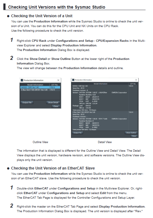
3. Upper level debugging
The computer is directly connected to PORT1 via Ethernet cable, and Sysmac Studio software is used to complete project configuration, programming, simulation, and online debugging.
Power System Design (Key Points of the Manual)
The power supply of the whole machine is divided into unit power supply (internal circuit power supply) and IO power supply (external sensor/load power supply completely separated), and it is strictly prohibited to mix them with the same power supply.
Unit power supply (for CPU, NX, X-BUS internal chips)
The native NX bus power supply capacity of the CPU is 10W, and additional NX power modules are installed for segmented power supply when the total power consumption of the rack NX exceeds the limit; The total power consumption limit of the X-BUS module is 50W, which is uniformly output by the CPU unit power supply. Recommend the S8VK series SELV safety power supply.
IO power supply (external sensor, solenoid valve load)
Distributed power supply from NX bus through additional IO power modules, with a maximum load limit of 10A for single segment bus IO, and segmented installation of IO power units in scenarios where current/voltage drop exceeds the standard and multiple voltages are mixed. It supports external separate power supply to module terminals.
Selection points: Calculate the power consumption and surge current of each module, match with air switches/fuses, and mark different current melting time standards.
Description of CPU body components
DIP DIP (4-digit): Safe mode boot, SD automatic program download, whole machine SD backup/restore, normally all OFF;
Status LED
POWER: Power supply; RUN: Running; ERR: Fault; BUSY: Built in non-volatile storage for writing;
SD-PWR/SD-BUSY: SD card power and read-write status;
Three independent LINK/RUN/ERR indicator lights for easy communication troubleshooting;
Terminal: 8-position detachable spring terminal, DC24V+grounded;
SD card: supports program upload and download, recipe storage, fault logs, FTP access. To insert or remove it, the SD power switch must be turned off and the indicator light must be turned off before removing it;
Backup battery CJ1W-BAT01: not provided at the factory. After installation, the software will enable low voltage detection, with a lifespan of 5 years. Power off maintenance requires powering on the main capacitor 5 minutes in advance to store electricity.
Installation specifications
DIN35 guide rail should be installed upright, and inverted/side installation is prohibited; Control cabinet environment: 0~55 ℃, humidity 5~95%, no condensation, away from dust, corrosive gases, high-power frequency conversion equipment, and a distance of ≥ 200mm from high-voltage components;
Accessories: PFP-M/CLIPFIX rail stopper, fixed at both ends of the rack to prevent movement;
Module assembly: When the power is turned off, the buckle is spliced and the locking sound is heard before the installation is considered to be in place. The NX/X-BUS is assembled one by one, and the pre installed guide rail cannot be installed in the whole row;
SD/Battery Disassembly and Assembly Specification: Anti static operation, SD is strictly prohibited from being disconnected and unplugged during reading and writing.
Wiring specifications
Separate wiring for unit power supply and IO power supply, with a grounding resistance of ≤ 100 Ω at the grounding terminal;
EtherCAT/EtherNet uses Category 5e and above shielded Ethernet cables, shielded single point grounding;
Spring terminal specifications for crimping, cable specifications ranging from 0.08 to 1.5mm ², and direct insertion of bare wires is strictly prohibited;
Power on sequence: PLC unit power supply first → peripheral IO power supply later; Power off in reverse to avoid instantaneous power on errors.
Power on/off timing and safety points
Power on: The CPU self-test takes several seconds, and during the startup phase, the rack DO is forcibly turned off. The EtherCAT slave output is determined by the slave parameters;
Power failure judgment: If the power supply is below 20.4V and lasts for 2-4ms, it will be judged as power failure. The program will be terminated immediately, the rack DO will be cut off, and SD writing will be stopped;
Safety design: Emergency stop and hardware interlock must be externally hard wired and cannot rely solely on PLC programs; Abnormal output adhesion, bus disconnection, etc. require an external safety circuit for backup;
Before modifying programs online or forcing IO, it is necessary to confirm the safety of the equipment on site.
Fault diagnosis and maintenance
1. Fault viewing method
Panel indicator light+Sysmac Studio online fault code check+system event log, divided into major faults (complete machine shutdown), partial faults (corresponding functional module shutdown), and minor alarms;
2. Daily inspection
Regularly clean the dust, check the wiring fastening, check the battery low voltage alarm, and SD life warning (software monitoring of storage card aging is available for models that meet standards);
3. Whole machine replacement
Simply insert the same model CPU into the SD card containing the project to restore the program, and recalibrate the servo origin data as needed.