BECKHOFF EL2911/EL2911-2200 TwinSAFE Safety Potential Supply Terminal Manual
Overview of System Architecture
Standard EtherCAT Terminal System
The entire I/O station consists of EtherCAT couplers and several terminal modules, with DIN35 rail snap on installation and tool free spring wiring;
E-Bus: Module side shrapnel transfers bus data and 5V power supply;
Power supply contacts: horizontally connected 24V power bus, EL91xx and other feeding terminals can cut off the bus and divide independent potential groups;
PE protection contact: prioritize conducting to ground, withstand 125A short-circuit current, and disconnect during insulation testing to avoid false alarms.
Core principles of TwinSAFE security system
FSoE (Safety over EtherCAT): Black channel safety protocol, safety data reuse standard EtherCAT bus, not separately wired;
Safety level: The whole machine meets IEC 61508 SIL3, EN ISO 13849 Cat.4/PL e, safety input SILCL3, safety output SILCL2;
System architecture: The safety logic unit (EL6910/EK1960) serves as the master station, and the TwinSAFE I/O terminals (EL1904/EL2911, etc.) serve as the slave stations; Up to 65535 secure nodes per network, supporting 512 FSoE communication links;
Fail Stop core rule: In case of any hardware, communication, or line failure, the system will forcibly cut off the safety output, enter a power-off safety state, and eliminate dangerous working conditions.
EL2911 Product Complete Introduction
Core differentiation between two models
|Model | Built in local security logic | Location|
|EL2911 | Support, can be used as an independent safety controller | With 4 safety inputs and 1 10A safety potential output, it can run safety programs locally or as a regular safety slave station|
|EL2911-2200 | No built-in logic, only pure IO slave station | Can only be used in conjunction with external TwinSAFE logic master stations such as EL6910, unable to independently run safety engineering|
Hardware Function Positioning
The module width is 24mm, and the E-Bus bus bus potential group starting terminal (there is no through power contact on the left side, and a new 24V power supply zone is opened from this module);
Hardware integration: 4 dual channel safety digital inputs (with diagnostic test pulses)+1 high-power safety output (bus power contact, maximum 10A);
Typical access devices: emergency stop button, safety door, dual hand switch, safety grating, position switch and other passive contact safety sensors;
The safety output can directly supply 24V power to all standard EtherCAT terminals of the same potential group, achieving safe disconnection of the entire area.
Electrical key parameters
Power supply: 24VDC (-15%~+20%), typical static power consumption of the module is 2.7W;
Input level: 0~5V is logic 0, 11~30V is logic 1, in compliance with EN61131-2 Type 3;
Safe output load upper limit of 10A, with external power supply detection (external voltage>5V after output shutdown to determine fault);
Cable: Shielded/unshielded cable with a maximum length of 100m and a wire diameter of 0.75/1mm ²;
Response: Typical 4ms input read time, fault response determined by watchdog duration;
Isolation: 500VDC electrical isolation between channels and E-Bus, no isolation between channels.
4. Environmental and mechanical indicators
Operating temperature: -25 ℃~+55 ℃; Storage and transportation -40~+85 ℃; Internal chip shuts down globally when temperature exceeds 110 ℃;
Protection level IP20, only for use inside the control cabinet;
Anti vibration and impact comply with EN60068, tested for resistance to industrial corrosive gases;
Size 24 × 100 × 68mm, weight approximately 98g.
Safety Failure Index (20-year Life Cycle)
PFHd=4.50E-09,PFD=5.00E-05, High diagnostic coverage DC, HFT=1;
No mandatory periodic verification testing is required throughout the entire lifecycle;
The probability of safety failure due to prolonged use has significantly increased, posing a risk of equipment injury.
4. Rigid requirements for wiring anti power feeding
The downstream standard terminal circuit of the module prohibits reverse voltage feeding and provides four compliant wiring solutions: independent shielded cables, cabinet wiring, independent grounding for each line, and armored fixed wiring; External independent power loads are prohibited from being connected to this potential group.
4. Panel LED status light
Input1~4 green: corresponds to the safety input contact being conductive and lit up;
Output1 Green: Safe output 24V power supply enabled;
Diag1 (green), Diag2/3/4 (red): distinguish between environmental voltage, temperature, dual core faults, global shutdown, communication faults, and differentiate fault types through flashing codes;
Diag Out red: Safety output circuit fault alarm.
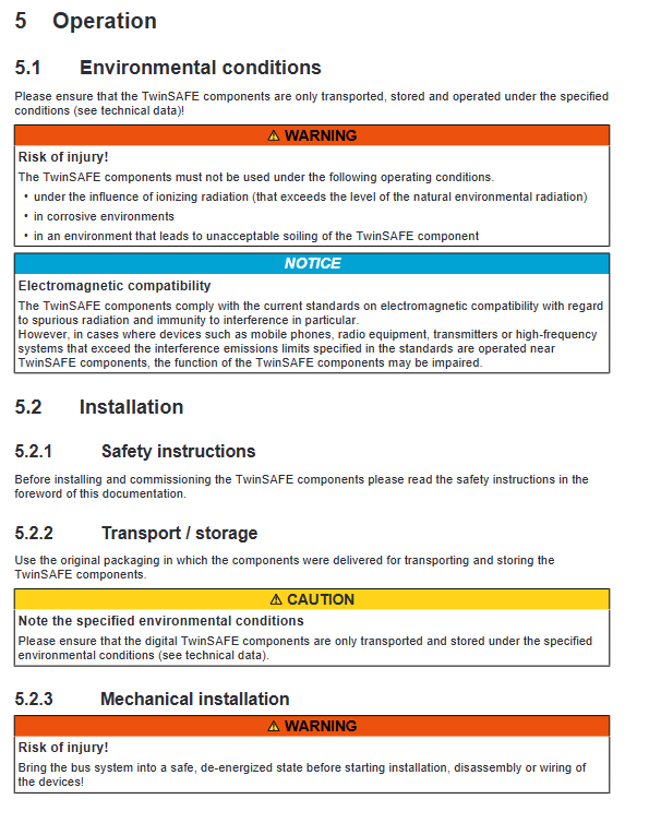
Installation and electrical wiring
Mechanical installation specifications
ESD anti-static requirements: discharge static electricity before operation, do not touch the internal shrapnel, and EL9011 end caps must be installed at the end of the I/O station;
The guide rail is only installed horizontally, and a 20mm convective heat dissipation space is reserved above and below the module; The high heating terminals (EL6910/EL2904) cannot be arranged closely to the coupler and need to be separated by low-temperature modules;
Disassembly and assembly: After power off, pull down the orange lock buckle to release the rail buckle, insert and remove the module laterally, and do not press the LED area;
Use countersunk screws for the guide rail to avoid interference with the module locking mechanism.
Electrical wiring specifications
Spring terminal compatible with 0.08-2.5mm ² cable, stripping 8-9mm;
Terminal definition: 4-channel dual channel safety input (+test pulse/- signal), two-way parallel safety power output, 24V and 0V power supply terminals;
Wiring separation: The safety signal line is laid in separate slots with the motor and strong electric power cable to avoid crosstalk and false alarm of test pulses;
Surge protection: Install surge filters on the power supply circuit and classify the voltage as overvoltage category II;
Disconnect the PE grounding contact before insulation testing to prevent false alarms from the insulation tester.
TwinCAT Safety Engineering Configuration Full Process
Hardware addressing: Set a unique FSoE address from 1 to 1023 with a 10 bit DIP dip code on the left side of the module, which cannot be duplicated on the same network; Address 0 is invalid;
Engineering differentiation:
EL2911: Two modes: ① Local safety logic (Safety Editor downloads program to module, runs independently) ② Normal FSoE slave station (with EL6910); Switching requires clearing the module security engineering and re powering on;
EL2911-2200: Can only serve as a slave station, without local logic;
Alias Device: Import I/O tree or manually create secure channel mapping, bind FSoE communication link;
Core CoE security parameters (0x8000/0x8010/0x8011):
Input filtering time (default 1.4ms for single channel), diagnostic pulse width, and pulse frequency division;
Output cross short circuit detection delay and enable standard output logic;
Prohibit arbitrary modification of CoE objects, as it may trigger a global security shutdown
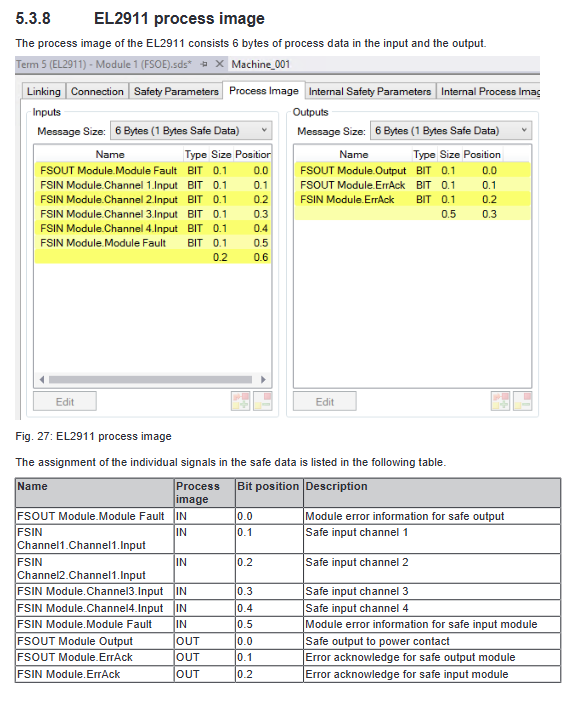
Process image: 6 bytes each for input and output, including 4 secure input bits, output enable, module fault, and fault confirmation flag;
Calculation of Safety Response Time
Typical response: sensor delay+input module 4ms+3x EtherCAT cycle+logic cycle+output delay; Example total typical 48ms;
Worst case fault cut-off time: Two communication watchdog duration+actuator delay, for example 50ms, to meet the emergency stop safety cut-off time limit.
Complete diagnostic system
Hardware LED flashing fault code: distinguish between high and low temperature of power supply, chip failure, functional block error, FSoE communication interruption;
CoE diagnostic history 0x10F3: Stores up to 64 timestamp fault logs, including fault types and parameters; Configurable fault automatic transmission of EtherCAT emergency message;
TwinCAT software Diagnosis interface: capable of refreshing, exporting, filtering information/warning/error logs, and supporting fault confirmation.
Maintenance, disassembly, and scrapping
The whole machine is free of daily maintenance, and severe pollution requires sending it to the original factory for cleaning;
Disassembling the machine requires the entire machine to be powered off, and the cables and modules must be removed in order;
Scraping follows the WEEE electronic waste regulations, with metal, plastic, and circuit board classified for recycling, and batteries treated separately; Can be sent back to the original factory of Beifu for professional destruction.