BECKHOFF EL5102 Incremental Encoder Terminal Manual
Product Overview
core positioning
EL5102 is a dual channel universal incremental encoder EtherCAT terminal, with a single module independent dual encoder acquisition channel. It is compatible with three types of incremental encoders: RS422 differential, TTL single ended, and open collector. Each channel has an independent 32-bit orthogonal counter and integrates advanced motion acquisition functions such as latch, gate control, speed measurement, cycle measurement, micro segmentation, and timestamp. It is installed on DIN rail IP20.
Core electrical technical parameters
Number of channels: 2 independent A/B/C encoder channels;
Encoder power supply: Each channel can be software switched to 5V/12V/24V output, with a maximum of 0.3A per channel;
Counter: default 32-bit, switchable 16 bit; Orthogonal 1/2/4 harmonics can be configured;
Maximum counting rate:
RS422 differential: 4x 20 million increments per second (5MHz)
TTL single ended: 4x 4 million increments per second (1MHz)
Open Collector: 4x 400000 increments/second (100kHz)
Additional inputs: independent 24V Latch latch input and Gate gate input for each channel; 5V encoder fault status input;
Isolation: The E-Bus bus is electrically isolated from the encoder side at 500VDC;
Typical power consumption of E-Bus is 210mA; the overall size is 27mm wide;
Environment: Operating at 0-55 ℃, storage and transportation at -25~+85 ℃, humidity ≤ 95%, no condensation;
Certification: CE, cULus, UKCA; Vibration and impact comply with EN60068.
EL51xx series horizontal comparison
The manual includes a comparison table for the EL51xx product line, distinguishing between single/dual channels and whether it supports C-zero pulse Latch/Gate、 The EL5102 has differences in speed measurement, fine segmentation, timestamp, and wire breakage detection functions. It belongs to a dual channel fully functional model, and both channels fully support all advanced acquisition functions.
Basic principle of incremental encoder
The incremental encoder outputs two phases A/B with a phase difference of 90 °, where C is the zero mark pulse per revolution;
Steering determination: A leading B=forward, A lagging B=reverse;
Frequency doubling rule:
1x: Only counting the rising edge of phase A
2nd harmonic: A-phase rising+falling edge
4x: All A/B edges, resolution increased by 4x
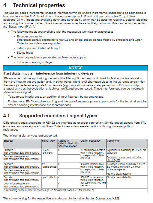
Signal type differentiation:
RS422 differential (A/A ̅, B/B ̅, C/C ̅): Strong anti-interference, suitable for long lines, supports diagnosis of broken wires and short circuits;
TTL single ended: only A/B/C, no reverse differential, no disconnection detection;
Open Collector collector open circuit: internal pull-up 5V, weak anti-interference of long wires, no wire breakage detection.
Hardware functional characteristics
Three encoder mode parameter configurations
Set the channel working mode through CoE index 0x80n1:1D to distinguish between encoder/pulse generator scenarios. In pulse generator mode, phase B is only used to determine the counting direction.
Dedicated input function
Latch external latch input (24V Type3 input, minimum pulse width>1 μ s): External trigger instantly latches the current count value for synchronous positioning (limit, probe acquisition); Support single lock/continuous lock mode, which can suppress mechanical switch jitter;
Gate control input: can be used as a counting enable, second channel latch trigger;
Status fault input (5V pull-up input): Encoder fault signal connected, low level represents encoder alarm; Only supports external pull-down fault output encoders.
Encoder power supply configuration restrictions
The default output is 5V; to modify 12V/24V, the password 0x72657375 (ASCII user) must be written to unlock the CoE parameter. Before modifying, confirm the encoder withstand voltage to avoid burning the sensor.
EtherCAT Communication Fundamentals
Hardware communication rules
EtherCAT standard CAT5e Ethernet cable, with a maximum output of 100m per segment; E-Bus bus coupler has a maximum output of 2A, and if the bus current is insufficient, an EL9410 feeding terminal needs to be installed;
Dual watchdog mechanism: SM synchronization manager watchdog, PDI process data interface watchdog, automatically enters a safe state upon timeout, and the time can be configured through the ESC register;
EtherCAT five state machine: Init → PreOp → SafeOp → Op → Boot (firmware upgrade specific), with differentiated communication permissions for each state;
Core partition of CoE object dictionary
0x1000: Device read-only information (model, firmware, serial number, eBIC);
0x80n0/0x80n1: Channel configuration parameters (encoder mode, frequency doubling, filtering, power supply voltage, latch settings);
0x6000 TxPDO (input): count value, latch value, speed, fault bit, timestamp;
0x7000 RxPDO (output): Counter reset, set value, latch enable;
Parameter storage: default writing to EEPROM, NoCoeStorage can be enabled to prevent cyclic writing and protect chip lifespan.
Distributed Clock
The module supports DC synchronization, with a clock accuracy of 1ns and a bus master station synchronization error of<100ns. The latch and count can be synchronized with EtherCAT cycle precise timestamps, making it suitable for high-speed synchronous acquisition scenarios.
Installation and wiring
ESD anti-static mandatory requirements
Release static electricity before operation, and do not directly touch the E-Bus spring on the side of the module; EL9011 end caps must be installed at the end of the I/O station to ensure anti-static and IP protection.
DIN Rail Installation Specification
Standard 35mm EN50022 guide rail, horizontal priority, full angle compatibility; Reserve a 20mm heat dissipation gap above and below;
Disassembly and assembly: Press down on the orange unlocking buckle and pull out the rear side of the separation module; Bus terminals should not be stacked continuously with more than 2 passive modules to avoid E-Bus signal attenuation;
The guide rail must be reliably grounded to PE, and the grounding contact should be disconnected before insulation testing to prevent false alarms.
Terminal wiring specifications
Spring cage terminal, compatible with 0.08-2.5mm ² cable, stripping 8-9mm; encoder must use twisted pair shielded cable, shielded single point grounding to suppress EMI interference.
Complete wiring diagrams for three types of encoders
The manual provides complete terminal wiring definitions for three types of encoders/pulse generators: RS422 differential, TTL single ended, and Open Collector collector open circuit, distinguishing between two types of connections with and without C-zero pulse.
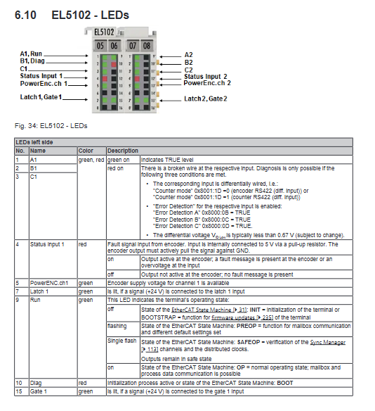
LED status indicator light
Run green light: EtherCAT status (off=Init/Boot, flashing=PreOp, single flash=SafeOp, constantly on=OP);
Diag red light: module hardware/communication failure;
A/B/C traffic lights: corresponding to channel signals, the red light is always on in RS422 mode, indicating A/B/C disconnection/short circuit;
PowerEnc green light: encoder power output is normal;
Latch/Gate/Status indicator light: corresponds to the external input level status.
scrap disposal
The equipment belongs to WEEE electronic waste, with circuit boards and metal casings sorted and recycled, and built-in CR2032 button batteries separately insulated and recycled.
TwinCAT Debugging Quick Start
Complete coverage of TwinCAT2 (System Manager+PLC Control) and TwinCAT3 (VS Integrated Environment) two complete debugging processes:
Pre steps: Install EtherCAT real-time network card driver and update ESI device description file (ESI updater tool);
Two configuration modes:
Offline configuration: Manually add EL5102 without hardware connection and plan IO mapping in advance;
Online scanning: After the hardware is powered on, the scanning bus automatically identifies the terminals;
I/O and PLC variable binding process: Add EtherCAT device → Scan terminals → Import PLC project → Variable linking PDO process data;
PLC supports all languages of IEC61131-3 (ST, LD, FBD, etc.), and the manual provides structured text examples;
Function block library: TcEtherCAT.lib provides dedicated function blocks for reading BIC, EtherCAT status, and CoE read/write.
Description of supporting tools
ESI XML: Device description file, missing may result in inability to recognize terminals, official website can be updated;
FoE firmware upgrade: Update MCU (. efw) and FPGA (. rbf) firmware in Boot state, supporting single/batch upgrades;
PLC automatically generates equipment structure: TwinCAT can generate EL5102 channel data structure with one click, directly reading count values, speed measurement, and diagnostic information.
EL5102 dedicated function configuration
Basic counting function
32-bit counter reading, software reset, and pre designed value writing;
Real time feedback of rotation direction from the steering detection position;
Counter latch and hardware Latch freeze values that do not change with axis movement;
Advanced measurement function
Frequency/cycle measurement: 10ns high-precision sampling;
Speed calculation: PLC directly reads real-time speed values;
Duty cycle evaluation;
Micro innovation: 1/256 subdivision improves low-speed positioning accuracy;
Timestamp: A/B edge, C zero pulse, Latch trigger all come with high-precision DC timestamp;
Adjustable digital filtering: suppresses motor interference pulses and avoids false counting;
Signal rationality verification, automatic fault setting for abnormalities.
Diagnostic system
Real time channel fault location: wire breakage, short circuit, signal overload, encoder power supply abnormality;
CoE historical fault log 0x10F3, storing 64 timestamp alarms;
EtherCAT Working Counter cycle communication diagnosis, quickly locate bus disconnection and terminal offline;