BECKHOFF EP20xx/EP28xx IP67 EtherCAT Box Digital Output Module
Overview of EtherCAT Box Products
Product positioning
Different from the EL series terminals inside the cabinet, the EP series is an IP65/66/67 on-site integrated bus box that does not require an intermediate coupler. The EtherCAT bus is directly cascaded to the equipment manipulator and assembly line rack, saving control cabinet wiring; The outer shell is made of PA6 nylon, fully sealed, waterproof and dustproof, and supports M8/M12/D-sub/multi pin heavy-duty actuator connectors.
The power supply is divided into two independent power sources:
Us: Bus, main control logic, sensor auxiliary 24V;
Up: The digital output load is 24V, and the two power sources are isolated/shared by model. The power supply interface can be cascaded to transmit to the next station.
2.2 Classification of Full Series Models and Summary Table of Core Parameters
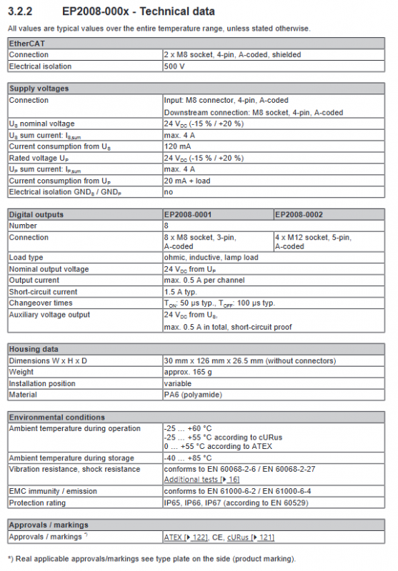
1) EP20xx 8-channel digital output (single box with 8 channels)
Model Number of Channels Single Current Total Output Current Joint Form Core Features
EP2008-0001 8DO 0.5A 4A 8 × M8 Economy Type No Diagnosis
EP2008-0002 8DO 0.5A 4A 4 × M12 Economy Type No Diagnosis
EP2008-0022 8DO 0.5A 4A 8 × M12, single channel per M12
EP2028-0001 8DO 2A 4A 8 × M8 high current no diagnosis
EP2028-0002 8DO 2A 4A 4 × M12 high current no diagnosis
EP2028-0032 8DO 2.8A 16A 8 × M12 high-power total current, supporting TwinSAFE interference free potential group
EP2038-0001 8DO 2A 4A 8 × M8 with broken/short circuit diagnosis
EP2038-0002 8DO 2A 4A 4 × M12 with broken/short circuit diagnosis
EP2038-0042 8DO 2.4A 16A 8 × M12 full channel independent diagnosis, switchable diagnostic function, DC synchronization
2) EP28xx high-density 16/24 channel digital output
Model Channel Single Current Total Current Connector Features
EP2809-0021 16DO 0.5A 4A 16 × M8 high-density economic type
EP2809-0022 16DO 0.5A 4A 8 × M12 (2 channels per port)
EP2809-0042 16DO 0.5A 16A 8 × M12, 7/8 power supply TwinSAFE compatible
EP2816 series 16DO 0.5A 4A ZS2001 terminal/M16/25 pin D-sub with grouped short circuit diagnosis, IP20 wiring model
EP2817-0008 24DO 0.5A 4A 25 pin D-sub 24 channel maximum density, grouped fault indicator light
EP2839-0022 16DO 0.5A 4A 8 × M12, M8 bus can diagnose single channel switch disconnection/short circuit
EP2839-0042 16DO 0.5A 16A M12 bus, 7/8 high-power power supply TwinSAFE adaptation, independent channel diagnosis
General hardware features
Bus interface: Green M8/M12 shielded EtherCAT port, IN input and OUT cascaded, Auto MDI-X automatically adapts to straight/cross CAT5e cables; Flashing lights for each L/A link and a Run status light for the entire machine (four state indication of Init/PreOp/SafeOp/OP).
Power interface: Black M8 (small power 4A)/7/8 inches (large power 16A), pins Us logic power, Up load power, GND, FE functional ground; The power supply can be connected in series to the next station.
Output indicator light: green output lights up for each channel; Additional red fault light for diagnostic purposes (short circuit/disconnection/undervoltage alarm).
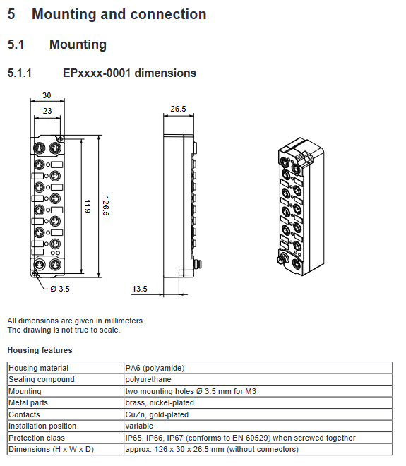
The shell size is divided into narrow (30mm wide), wide (60mm), and extended 150mm high-power shell; Material PA6, polyurethane seal, meets IP65/66/67 (joints must be equipped with original waterproof caps).
Electrical isolation: EtherCAT bus and IO side 500V isolation; Wide temperature operation -25~+55 ℃, storage -40~+85 ℃, vibration and shock comply with EN60068.
Basic principles of output protection
Overload/Overheat Protection: Single channel short circuit current limiting, long-term overheating automatically shuts off the channel, and can automatically recover or require PLC reset after cooling; Multi channel simultaneous overload and complete machine temperature control shutdown.
Inductive load absorption: Equipped with a built-in freewheeling circuit to suppress electromagnetic valves and turn off high-voltage spikes in coils, external RC/pressure-sensitive protection is recommended for high-power inductors.
Output graded current limiting: Distinguish between three levels of protection logic: short-term overload, continuous overload, and short circuit.
Mechanical installation and electrical wiring
Installation specifications
Fixed method: narrow shell M3 screws, wide shell M4 screws, matched with ZS5300 stainless steel prefabricated installation guide rails; The installation hole also serves as the FE function grounding, ensuring low impedance contact with the machine ground.
Protection requirements: Idle connectors must be tightened with waterproof protective caps, and only complete cables/caps can maintain IP67; ATEX explosion-proof scenarios must be equipped with BG2000 protective outer boxes.
There is no mandatory restriction on installation orientation, but there is reserved heat dissipation space around it; Cable torque specifications: M8=0.4Nm, M12=0.6Nm, 7/8 “=1.5Nm.
FE functional grounding: EPxxxx-002x/0042 wide shell must be reliably grounded through installation screws to eliminate EMI interference.
Complete wiring definition
EtherCAT bus M8/M12 pins are uniformly Tx+/Tx -/Rx+/shielded, and the cable follows EN61918 color code, with a minimum CAT5e shielded twisted pair and a maximum length of 100m per segment.
Differentiate the power interface between M8 (4A) and 7/8 “(16A), clarify the Us, Up, GND, and FE pins, provide voltage drop curves for cables of different diameters, and refer to the selection of long cables.
Digital output connector subdivision: M8 single channel, M12 dual channel, M16/25 pin D-sub heavy-duty, ZS2001 spring terminal, each model is separately illustrated with 2-wire/3-wire actuator connections.
Mandatory wiring requirements: power cables and buses should be laid separately, and the shielding layer should be grounded at a single point; UL certified equipment can only use isolated 24V Class2 power supply for power supply, and multiple Class2 series and parallel connections are prohibited.
ATEX explosion-proof usage conditions
Suitable for II3G Ex nA nC IIC T4, only 0-55 ℃ environment;
Must be equipped with BG2000 protective casing, cable temperature resistance matching equipment heating;
Only plug and unplug the connector in power-off state, and the instantaneous overvoltage cannot exceed 40% of the rated voltage;
The explosion-proof label of the entire machine is printed on the side nameplate, accompanied by official ATEX supplementary documents.
UL compliance constraints
Power supply limited to isolated 24V Class2 power supply, maximum 4A fuse; Prohibit access to telecommunications networks; The upper limit of operating temperature is 55 ℃, and the nameplate is marked with cURus.
Debugging, configuration, and fault behavior
TwinCAT Integration Process
Install the corresponding ESI description file, scan and identify the EP substation; Support offline pre configuration and online automatic hardware reading.
The PDO process image is divided into: digital output data, channel diagnostic bits, and device global status (overheating, Us/UP undervoltage, synchronization errors).
Supports two types of PDO templates: basic output only and full version with all wire breakage/short circuit diagnosis.
Communication Fault Safe State Core Function
When EtherCAT is lost, powered on for initialization, or manually switched to PreOp, the output enters a safe value (all are set to false by default);
The CoE parameter can independently configure safety status values for a single channel, disable safety functions (maintain current output when disconnected), and set safety delays;
Applicable models: EP2038-0042, all EP28xx series.
Output short circuit/undervoltage fault response (EP28xx diagnostic model)
Short circuit two modes (Coe F800:01 switching):
Mode 0 (default): Single channel short circuit → All outputs of the whole machine are turned off, requiring PLC reset word to restore;
Mode 1: Only the fault channel is cut off, and the short circuit is eliminated and automatically restored; Customizable short circuit detection delay.
Under voltage of Up load power supply: detected rear channel fault position, all outputs are forcibly turned off, and can be reset automatically/manually.
Advanced Diagnostic Switch (EP2038/EP2839)
By default, the disconnection and 24V short circuit detection are turned off at the factory, and can be turned on channel by channel through the 80nxx series CoE parameters:
Output off state disconnection detection (load<1mA)
Output open state disconnection detection
Output for 24V short circuit detection
Real time storage of fault information in TxPDO diagnostic bits and 10F3 diagnostic logs (up to 16 timestamp fault records).
Restore factory settings
The Coe index 1011 sub index is written with a fixed hexadecimal password 0x64616F6C, and all machine parameters, diagnostic configurations, and security settings are restored to factory settings.
Equipment retirement process
Cut the SafeOp/Init of the whole machine, cut off the Us/UP power supply, unplug all connectors, and remove the fixing screws; Electronic waste is classified and recycled according to WEEE regulations.
Complete description of CoE parameters
The manual uses EP2038-0042, EP2816, EP2817, and EP2839 as templates to fully list all object dictionaries, which are divided into four categories:
Device read-only information (0x1000~0x10FF): model, software and hardware version, serial number eBIC、 Diagnostic logs and distributed clocks;
Channel configuration parameters (x800 series RW read-write): diagnostic switch for each channel, safety status enable, safety value, fault delay;
PDO mapping object (0x1600 Rx output, 0x1A0 Tx diagnostic);
Global device settings (F800, etc.): short-circuit protection mode, undervoltage threshold, temperature monitoring.
Each parameter is labeled with read and write permissions, factory default values, and data length, accompanied by examples of TwinCAT CoE online interface operations.