Hirschmann OCTOPUS OS20/OS24 Network Managed IP65/IP67 Industrial Switch Installation Manual
Product overall definition and model code
Product line differentiation
Model PoE Capability Port Overall Configuration
OS20 without PoE 9-way M12 100Mbps electrical port (2-channel uplink T5 M12)
OS24 PoE+IEEE802.3at 9-way M12 100Mbps, with a total of 8 ports 2-9 supporting PoE. The total PoE output limit of the whole machine is 61.6W
Complete model code segmented interpretation
Series: OS20 (without PoE)/OS24 (PoE+)
00=no gigabit port; 08=8 PoE ports
09=9 100M M12 electrical ports
00=no gigabit; T5=100Mbps M12 upstream port (2)
Temperature range T: -40 ℃~+70 ℃ Wide temperature range
Power supply: A (5-core M12, 9.6-60VDC), F (5/7/8 connector 16.8-60VDC), N (4-core 7/8 connector 50.4-138VDC locomotive high voltage)
Certification E (Rail Vehicle)/F (Rail+Ship GL)
B Basic firmware, HH=IP65/67 sealed machine
Whole machine hardware layout (unified panel)
Power connector: A=5-core M12; F/N=7/8 industrial connector, dual redundant P1/P2;
FAULT passive M12 signal relay terminal;
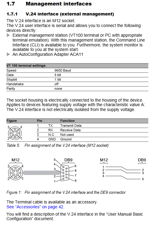
V. 24. Debug M12 serial port (ACA11 adapter/CLI console);
9 D-encoded M12 100Mbps electrical ports (8 ports PoE after OS24);
Global LED of the whole machine (P1/P2 power supply, RM ring network, FAULT fault);
Each port has an independent LS link, DA data, and PoE indicator light;
M3/M4 grounding screw, IP sealed housing, MAC/IP identification area.
Whole machine management method
Local: M12 V.24 serial port (9600 8N1), ACA11 configuration adapter;
Remote: Web pages Telnet; Batch operation and maintenance of HiDiscovery/Industrial HiVision;
Core software: HIPER Ring self-healing ring RSTP、 Port isolation, link monitoring, PoE power management.
Detailed parameters of the three major types of power supply
Type A (5-core M12 connector)
Rated 24-48VDC, operating range 9.6~60VDC, dual redundant, 0.6Nm tightening torque, standard ELWIKA 5-core M12 connector.
F-type (5-pin 7/8 “connector)
Rated 24-48VDC, wide range of 16.8-60VDC, suitable for PoE models; The power cord needs to pass through the matching magnetic ring for 3 turns, tightly adhere to the equipment to reduce EM interference, and have a torque of 2.5Nm.
N-type (4-pin 7/8 “locomotive specific)
High voltage DC 50.4~138VDC (nominal 72-110V), dedicated for rail locomotives, with a tightening torque of 2.5Nm, limited to installation in restricted machine rooms only.
FAULT Passive Relay Function
Normally closed contact, report disconnection in case of fault: loss of one/two power sources, interruption of port links, machine self-test fault, abnormal HIPER Ring network configuration; The web interface allows manual control of relay external alarm devices. Contact maximum 1A/48VDC resistive load.
Port specification (M12 D encoding)
Ordinary 100Mbps M12:10/100M, automatic negotiation/automatic line sequence/automatic polarity, Cat5e shielded cable up to 100m long; 4-pin D-code M12.
OS24 PoE port: IEEE802.3at 30W phantom power supply, 1/3, 2/4 wire pair output, total power limit of 61.6W, overload automatically cuts off port power supply; There is no electrical isolation between PoE ports, and the ring network needs to mix non PoE ports to avoid potential differences.
V. 24 Debugging M12: Define TX/RX/GND with 4 pins and adapt to VT100 terminals.
Complete definition of LED indicator lights
Global indicator light for the entire machine
P1/P2 green light is always on: corresponding power supply is normal; Extinguish=undervoltage;
RM Ring Network Manager: Off=Ring Network Closed; Evergreen=RM enabled, redundant ports disabled; Huang Changliang=redundant port activated; Flashing=Loop network wiring/configuration error;
FAULT red light is always on: there is a fault alarm; Extinguish=The whole machine is normal.
Single port indicator light
LS green light constantly on=link connected; Cycle 1 flash=port standby; 3 flashes=port closed;
DA yellow light flashing=transmitting and receiving data; No flicker=no flow;
PoE green light always on=terminal power supply; 1 flicker=complete machine power overload and power outage; 3 flashes=Web manually turns off PoE output.
Complete installation and wiring process
Open box inspection: Check the host, matching connectors, magnetic ring (F model), sealing protection screws, safety manual, and verify that the housing seal is not damaged;
Flat fixing: M5 screws for flat wall/cabinet installation, with reserved space for upper, lower, left, and right heat dissipation;
Grounding: M3/M4 grounding screw with tooth pad, ground wire ≥ 0.75mm ², priority grounding;
power wiring
Type A: 5-core M12 connected to dual DC+FAULT;
F-type: 7/8 power connector, power cord threaded through magnetic ring three times close to the body;
N-type: locomotive 4-core 7/8 high-voltage connector;
All connectors should be tightened with the specified torque, and unused interfaces should be equipped with sealing plugs;
Fault signal terminal M12 wiring;
M12 Ethernet cable access: Shielded Ethernet cable shell connected to equipment ground, strong and weak electrical wiring divided into slots, cross 90 ° to reduce interference;
Power on self-test: After about 30 seconds of power on, the whole machine self-test is completed, and the LED flashes in full sequence before it is ready.
Factory default basic configuration
IP address: default DHCP automatic acquisition;
Account: admin (read-write, password private), user (read-only, public); It is recommended to change the high-strength password for the first login;
V. 24 serial port: 9600 baud, 8 data bits, 1 stop bit, no checksum;
Port: auto negotiation enabled, PoE enabled by default;
Redundancy: RSTP enabled, HIPER Ring disabled, link alarm disabled.
Maintenance, temperature monitoring, and disassembly
The consumable parts are only FAULT relays, and the contact resistance is regularly checked in high-frequency scenarios;
The device CLI/Web can read the internal temperature, which is higher than the environment; The upper limit of the bottom plate temperature for PoE models is 90 ℃, and if the temperature exceeds the limit, the PoE power will be reduced;
Regularly check the integrity of M12 sealing plugs to avoid water and dust ingress; Official website firmware update fixes vulnerabilities;
Dismantling sequence: Disconnect all cables first → Remove the ground wire → Loosen the fixing screws and remove the entire machine; Immediately install protective screws on the idle interface.
Core mechanical and electrical technical parameters
Physical specifications
Fixed overall size, weight 1900g; IP65/IP67 protection, no fan; Flat M5 screw installation without DIN buckle.
Power supply and power consumption
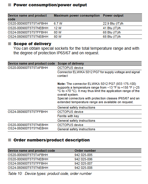
Type A: Maximum power consumption of 6.7W;
N high-voltage model: 12W;
The maximum power output of the OS24 PoE machine is 80W, and the upper limit of PoE output is 61.6W;
Input built-in slow melting non replaceable fuse, power down buffer>10ms.
Environmental conditions
Working temperature -40 ℃~+70 ℃; Storage -40~+85 ℃; Condensation can occur when the humidity is between 5% and 100%; The highest altitude is 2000m, with a pollution level of 2.
transmission distance
Shielding Cat5e twisted pair cables up to 100m.
Supporting accessories
Various M12 connectors, 7/8 power connectors, EMC magnetic rings, sealing protection screws, ACA11-M12 configuration adapters, M12 to RJ45 adapters, HiVision network management software.
Industry certification and implementation standards
Safety UL60950-1, CE, FCC; Rail transit EN50155/EN50121; Ship GL classification; Industrial EMC complete set of anti-interference standards; RoHS Environmental Directive.