Hirschmann OZD Profi G12DU/G12DK/G12DE ATEX1 PROFIBUS Fiber Optic Repeater Manual
Overall hardware architecture and core functions of the device
Definition of Hardware Channels (Unified Three Channel Design)
CH1: Electrical channel, RS485 PROFIBUS interface, terminal wiring;
CH2, CH3: Two independent ST (BFOC/2.5) fiber optic transceiver channels, duplex fiber optic networking;
Supporting terminal module:
Two redundant 24VDC power supply terminals;
FG functional grounding terminal;
FAULT passive relay alarm contact (F/NO/NC, normally closed fault disconnected);
CH2/CH3 optical power analog measurement terminal (external multimeter for light receiving level);
8-bit DIP dip switches: S0~S7, used for topology mode and terminal resistance configuration;
Status LED: System main light, CH1 electrical port light, CH2/CH3 light port light;
Whole machine isolation: power supply RS485、 Fiber optic circuit electrical isolation to eliminate the risk of potential difference explosion in explosion-proof areas.
2. Hardware differences among the three major models
|Model | Shell | Protection | Installation Method | Cable Interface|
|G12DU | Bare module without shell | IP40 | 35mm DIN rail/flat screw | Front terminal direct insertion|
|G12DK | Plastic explosion-proof shell | IP66 | Flat four hole fixing | M16/M20 PG waterproof gland outlet|
|G12DE | Stainless steel explosion-proof shell | IP66 | Flat double bracket fixation | M16/M20 metal explosion-proof gland|
3 core basic functions (universal for all topologies)
Full rate adaptive: automatically recognizes all PROFIBUS standard baud rates from 9.6kbit/s to 12Mbit/s, without the need for manual setting;
Signal shaping and regeneration: Reconstruct RS485 waveform, cascading up to 122 repeaters at most;
Fiber link echo monitoring (Echo): bidirectional detection of fiber breakage, automatic segmented isolation network for faults;
Redundant 24V dual power supply, with no load sharing between the two channels;
Optical port analog level detection terminal, quick on-site inspection of fiber attenuation;
Passive FAULT relay summary alarm: power loss, fiber breakage, bus short circuit, configuration error;
Built in RS485 terminal resistor, DIP one key on/off.
4. Three topology exclusive working modes (DIP dip switching)
Equipped with monitoring linear mode (factory default)
Enable echo detection+fault segmentation; After the fiber optic cable is broken, the network automatically splits into two independent subnets, with LED and relay alarms, and the fiber optic repair automatically merges. Suitable for the vast majority of explosion-proof bus projects.
Non monitoring linear mode
Disable echo detection, only compatible with third-party non Hirschman fiber converters, not recommended for standalone networking.
Redundant fiber ring mode
Double optical fibers form a loop, and when a single fiber breaks, it automatically switches to a linear configuration; All devices within the ring network must be coded uniformly; Need to adjust the PROFIBUS Slot time and HSA highest station address to adapt to the ring network delay.
Explosion proof and environmental mandatory use rules
Partition installation constraints
Zone 1 (Gas Explosion proof Zone 1):
G12DU must be installed in a cabinet with at least IP54 increased safety/explosion-proof; DK/DE can be installed directly, but when opening the cover for maintenance, power must be cut off or a hot work permit must be held; The maximum shell temperature in the environment is ≤ 60 ℃.
Zone 2 (Zone 2 gas):
DK/DE machine can be used directly; DU needs to be equipped with a compliant explosion-proof cabinet, with an outer shell IP ≥ 54.
Zone21/22 Dust Explosion proof: Only supported by G12DE stainless steel models, opening the cover must be completely powered off.
Safe zone: All three models can be freely installed, and DK can be equipped with a window shell cover for easy viewing of LED.
2 Explosion proof Hard Prohibitions
It is prohibited to plug and unplug optical fibers, terminals, and open covers while they are live within the danger zone; Only ST optical fibers can be plugged in with electricity in the safe zone;
The idle PG gland and fiber optic ST port must be sealed with original factory sealing plugs, otherwise the IP and explosion-proof will fail;
Cable temperature constraint: High temperature and explosion-proof cables must be selected for cable entrances above 70 ℃;
Shielding specification: PROFIBUS double shielded cables are fully grounded at both ends, and equipotential equalization cables are laid in parallel to eliminate ground circulation;
5. Inductive/relay loads must add absorption circuits to reduce EM interference and avoid explosion-proof risks.
environmental parameters
Working temperature: -20 ℃~+60 ℃; Storage -40~70 ℃;
Humidity of 10-100% without condensation, maximum altitude of 2000m; pollution level 2;
Fiber optic transmission: 50/125, 62.5 multimode 860nm wavelength, maximum transmission 3000m.
Complete installation, dialing, and wiring operation process
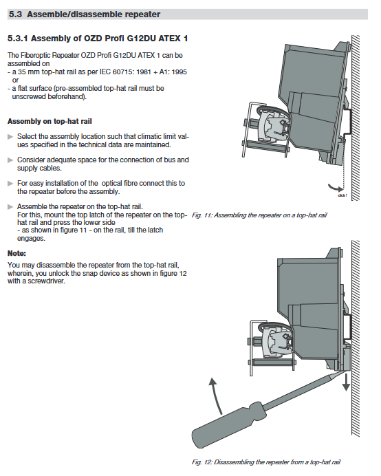
1. Mechanical installation
G12DU: snap on DIN rail installation, also removable rail bracket flat fixing;
DK/DE: Drilling plate fixation, locking shell screw torque of 2.5Nm;
All models must prioritize connecting the FG function ground wire, with a ground wire diameter of ≥ 0.75mm ²;
4 cables pass through the matching waterproof gland, which is locked with the specified torque and the sealing gasket matches the outer diameter of the cable.
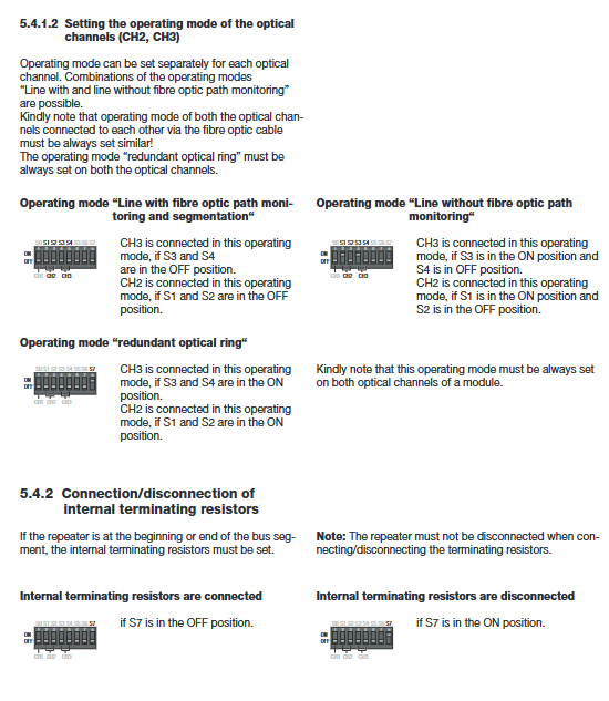
2 DIP dip configuration (power-off operation)
S0: CH1 electrical port mode OFF=enable bus monitoring (line/ring); ON=Off (star shaped center end dedicated);
S1/S2: CH2 fiber mode; S3/S4: CH3 fiber mode
Double OFF: with monitoring line type;
S1=ON S2=OFF: No monitoring line type;
S1+S2 both ON: redundant ring network;
S7: Terminal resistor OFF=matching resistors at both ends of the bus are turned on; ON=OFF;
S5/S6 reserved with no functionality.
3. Wiring specifications for four types of terminals
24V redundant power supply: Two independent SELVs 18~32VDC, no load sharing, single circuit power failure triggers FAULT alarm;
CH1 RS485 bus: DI A/DI B, DO A/DO B can be connected in series with the bus, and only the terminal resistors are open at the beginning and end of the bus; Double shielded PROFIBUS cable must be used;
FAULT relay: 30V/1A maximum load, normal F-FNC conduction, fault switching F-FNO;
Optical power measurement terminals CH2/CH3: high resistance multimeter measurement, distinguishing fiber loss levels (good/critical/failure) within the range of 0-900mV.
4 Fiber optic cabling requirements
Bidirectional ST duplex fiber, with cross docking for transmitting and receiving (A transmitter to B receiver);
The minimum bending radius meets the standard, and the idle ST is covered with a dust cap to prevent interference from stray light;
Fiber optic cables in the explosion-proof zone must be introduced into the housing through explosion-proof glands.
LED indicator status description
System system light
Evergreen: normal power supply, baud rate recognition completed;
Red and green flashing alternately: incorrect configuration of ring network parameters (slot/HSA mismatch);
Extinguish: No power supply/hardware failure;
CH1 (electrical port) yellow light: constantly on=bus connected device, off=bus open circuit;
CH2/CH3 optical port
Yellow light flashing: normal reception of fiber optic messages;
Red light constantly on/flashing: fiber breakage, reverse transmission and reception, power failure of the opposite end equipment;
After the red light is triggered, the FAULT relay will synchronously sound an alarm.
Detailed Description of Topology Structure
1. Linear topology (most commonly used)
Single chain series connection of multiple OZDs, fiber optic segmented isolation explosion-proof zone, supporting automatic fault segmentation; Maintain consistency in paired fiber channel dialing.
2-star topology
Multiple OZD electrical ports CH1 are connected in parallel on the central RS485 bus; Set the central device S0 to ON (turn off bus monitoring) to avoid false alarms across the entire network; All optical ports maintain linear mode.
3 Redundant Fiber Optic Loop Topology
All devices have their two optical ports switched to ring network mode; Automatic switching of fiber optic single point breakage line type; Supporting PROFIBUS parameter modification:
The number of retries by the main station is ≥ 3;
Calculate the slot time according to the manual formula (fiber length+OZD quantity+rate);
Reserve at least one blank address for the highest HSA station address (to prevent automatic ring closure after a malfunction).
4 Cross Explosion proof Zone Hybrid Networking
The explosion-proof equipment G12DE/G12DK in Zone 1 is connected to the safety zone OZD in Zone 2 through optical fibers, which act as isolation media to block the cross regional transmission of hazardous energy.
Troubleshooting (fault location+repair list)
1. Quickly investigate the logic
1. System light abnormality: Check the two 24V power supplies and terminal wiring;
2 CH1 light not on: RS485 bus disconnection, short circuit, incorrect terminal resistance configuration;
3. Red light at the optical port: fiber optic transceiver connection reversed, cable damage, power failure at the opposite end, excessive light attenuation (judged by measuring terminal voltage);
4. Frequent network disconnections: Check the shielding grounding, equipotential cables, inductance absorption circuit, and PROFIBUS Slot parameters.
2. Required information for manufacturer repair report
Complete equipment model, serial number, network topology, fiber length/type, DIP dialing status, measured voltage of each optical port, baud rate, and fault LED phenomenon.
Core Technical Parameters of Electrical and Mechanical Engineering
Power supply: 18~32VDC redundant input, overall power consumption ≤ 5W, maximum 200mA;
2 optical modules: 860nm multimode, transmission power -15dBm, reception sensitivity -28~-3ddB;
3 FAULT contacts: maximum 60VDC/1A resistive load;
4 Transmission: 9.6k~12M PROFIBUS, signal regeneration delay<6.5bit;
5 Protection: DU IP40, DK/DE IP66;
6 Weight: DU ≈ 1.5kg, DK ≈ 2.4kg, DE ≈ 3.7kg;
7 Torque specifications: The shell screws are 2.5Nm, and the explosion-proof gland is tightened according to the specified torque.
Maintenance, repair, and scrapping
1. Daily: Regularly clean the dust on the shell, check the cleanliness of the gland seal and fiber optic connector; Quarterly detection of fiber attenuation through optical measurement terminals;
2. Maintenance: There are no replaceable parts inside the equipment, and any malfunctions must be replaced by the original factory. Disassembly is prohibited;
3. Storage and transportation: use original factory packaging, in a dry and clean environment;
4 Scrap: The entire machine, optical fiber, and electronic components shall be disposed of separately in accordance with local hazardous waste regulations.
Supporting accessories
OZD SFK with window housing cover (for DK models only), ST duplex multimode fiber, explosion-proof PG gland, shielded PROFIBUS cable, DIN rail accessories, and matching diagnostic multimeter.