Basler SR4A/SR8A Analog Excitation Voltage Regulator
Core distinction between the two major product models (electrical power)
SR4A (low-power version)
Power input: 95~139Vac, 50/60Hz, 840VA;
Excitation output: continuous 63Vdc/7A, 1 minute strong excitation 90Vdc/10A;
The minimum DC resistance of the excitation winding is ≥ 9 Ω.
SR8A (high-power model)
Power input: 190~277Vac, 50/60Hz, 1680VA;
Excitation output: continuous 125Vdc/7A, 1 minute strong excitation 180Vdc/10A;
The minimum DC resistance of the excitation winding is ≥ 18 Ω.
Common electrical parameters
Voltage sampling: supports 120/208/240/416/480/600Vac, single-phase/three-phase sampling is optional, load ≤ 10VA;
Voltage regulation accuracy: The average error of the full load range is less than ± 0.5%; Temperature drift: temperature difference of only ± 0.5% at 40 ℃;
Response speed: 60Hz system<17ms, 50Hz<20ms;
Voltage regulation range: adjustable within ± 10% of rated voltage;
Parallel CT circuit: rated 5A secondary, load 25VA, single about 8% differential adjustment, three-phase about 6% differential adjustment;
The maximum power consumption of the whole machine is 60W.
Mechanical and Environmental Specifications
Dimensions: Height 292mm x Width 213mm x Depth 127mm, Weight 5.8kg; It is recommended to install vertically to ensure heat dissipation;
Working temperature: -55 ℃~+70 ℃; Storage -65 ℃~+100 ℃;
Anti vibration: 20~260Hz can withstand 5G vibration and meet the harsh working conditions of on-board generator sets;
Hardware structure: composed of electrolytic capacitors, silicon rectifiers, voltage regulators, resistors, and transformers, with extremely strong resistance to temperature, humidity, and vibration.
Model coding rules (SRxx-A-2-B-15-B-3-E)
Segmented meaning:
SR4A/SR8A: Excitation power level;
Parallel configuration: 1=no parallel circuit, 2=built-in adjustable sliding resistance parallel, 3=external parallel potentiometer;
Excitation relay: A without, B with sealed excitation relay;
Sampling type: 15 single-phase sampling, 16 three-phase Faston terminal sampling;
Shell: B with shell;
Voltage regulating potentiometer: 2 built-in, 3 external matching, 4 built-in with lock;
Excitation adaptation: A>150kW brushed units, B static excitation, E ≤ 150kW brushless excitation units.
List of optional accessories for core hardware
External voltage regulator potentiometer (175 Ω/2W, part number 03456);
Parallel adjustment potentiometer (part number 03469);
Low frequency protection module, EMI filter, isolation transformer, parallel CT, manual excitation module, V/Hz module, overvoltage protection, line voltage drop compensation, transient suppression filter, VAR/PF controller and other extended components.
Internal five basic working circuits
Whole machine closed-loop voltage regulation architecture:
Sampling circuit: collects the voltage of the generator bus, and the internal transformer has multiple tap positions to adapt to different voltage levels;
Error detection: Compare the sampled rectified voltage with the voltage stabilizing reference diode to generate a deviation signal;
Error amplification: amplifying voltage deviation;
SCR power control: thyristor regulates excitation output DC;
Stable compensation network (R4): damping oscillation, balancing response speed.
Two major reactive power balancing schemes for parallel operation (core function)
1. Reactive power adjustment (Droop, compatible with external network/isolated bus)
Principle: When the unit is loaded with inductive load, the regulator automatically reduces the voltage slightly, achieving natural sharing of reactive power among multiple units;
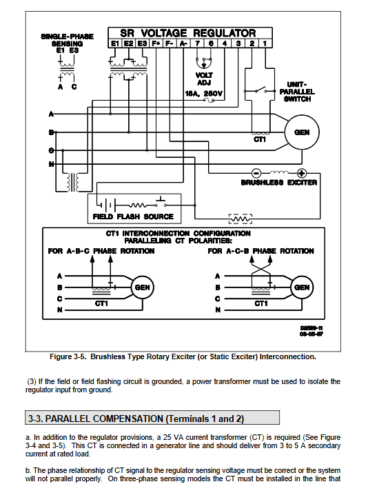
CT is installed in phase B, and the secondary signal is superimposed on the sampling circuit;
The voltage of a pure resistive load remains almost unchanged, while the voltage drop of an inductive load and the voltage rise of a capacitive load;
Single machine operation can short-circuit the CT circuit to close and adjust the deviation.
2. Cross current differential compensation (isolated bus only, prohibited from grid connection)
All CT units are connected in series at the beginning and end in a closed loop, with reactive power circulating currents canceling each other out and no drop in bus voltage;
When connecting to the external network, the CT series circuit must be disconnected and switched to differential mode;
The auxiliary contacts of each unit circuit breaker are used to split the differential loop.
Installation and wiring specifications
1. Installation requirements
Vertical installation is beneficial for heat dissipation, and the whole machine can be directly fixed to the unit housing; Minimum 16AWG copper wire for terminal cables.
2. Definition of key terminals
3. 4: AC working power supply for regulator;
E1/E2/E3: Terminal voltage sampling (single-phase E1E3, three-phase E1E2E3); Factory default 120V tap, can be opened to replace transformer terminals and adapt to voltage;
F+/F -: excitation output DC;
A -: Brush excitation machine auxiliary excitation terminal;
1. 2: Parallel CT secondary input;
3. Mandatory requirements for excitation resistance
When the excitation DC resistance is lower than the standard (SR4A<9 Ω/SR8A<18 Ω), a power resistor must be connected in series to avoid damaging the voltage regulator; The recommended no-load output is ≥ 10V to ensure stability.
4. Two types of excitation standard wiring
Brushed rotating excitation: using A-terminal, short-circuit excitation circuit adapted to short-circuit conditions;
Brushless/static excitation: does not use A -, relies on PMG or generator bus power supply.
5. Operation strictly prohibited
It is strictly prohibited to disconnect the excitation circuit under load to prevent high-voltage breakdown of the device; If shutdown is required, cut off 3/4 of the AC power supply and do not disconnect F+/F -.
Adjustable potentiometer function on the panel
R1 voltage regulation: clockwise boost, counterclockwise buck, ± 10% range;
R3 range reference: Lock the upper and lower limits of voltage regulation, factory calibration;
R4 Stable Damping: Clockwise stable (slow response, no oscillation), counterclockwise fast response, excessive voltage oscillation; No load is most prone to oscillation, and a stable margin needs to be reserved;
R25 parallel adjustment differential slip resistance: controls the amplitude of reactive power drop.
Whole machine operation process
1. Single machine no-load debugging
The prime mover reaches the rated speed and the residual voltage is sufficient to automatically start excitation; Perform magnetization without residual voltage (F+, A – external ≤ 125V DC current limiting power supply for short-term power supply);
R3 calibrates the rated voltage, R4 is adjusted to the oscillation free range;
Load testing is qualified if the voltage regulation error is less than 0.5%.
2. Low speed operation restriction
Long term below rated speed will damage the exciter and regulator, and low-frequency protection must be installed or 3/4 power supply must be disconnected.
3. Complete steps for parallel operation
Complete no-load and load tests on a single machine first, and verify the adjustment function;
Synchronization conditions: frequency, voltage, phase, and phase sequence are completely consistent;
After grid connection, active power is distributed through a speed regulator, and R1 is regulated to evenly distribute reactive power;
Fault differentiation: The uneven active power is caused by the speed regulator, while the uneven reactive power is caused by voltage regulation/CT polarity errors.
Field Flashing Operation
When the residual magnetism of the unit is insufficient to build pressure:
In the shutdown state, the positive pole of the DC power supply is connected to F+and the negative pole is connected to A – series current limiting resistor for short-term power supply; Internal diode isolation to prevent current backflow from damaging the magnetizing power supply.
Maintenance, spare parts, and troubleshooting
1. Preventive maintenance
Regularly clean dust, tighten terminals, and prohibit washing with water; The circuit board has a protective coating, and it is recommended to replace the entire machine if there is a malfunction.
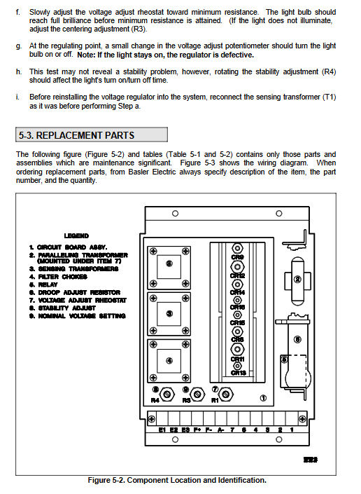
2. Core spare parts
Main control circuit board, SCR thyristor, rectifier diode, sampling/parallel transformer, filtering choke, excitation relay, various adjustable resistors, etc., divided into SR4A/SR8A two sets of material lists.
3. Simple bench testing of the entire machine
Connect the corresponding AC power source and load bulb externally, rotate R1 to observe the brightness change, and quickly determine the quality of the voltage regulating circuit.
4. Typical Fault Comparison Table (covering all common problems)
Voltage cannot build up: insufficient residual voltage (magnetization), incorrect sampling tap, open circuit wiring, insufficient speed;
Rapid drop after pressure rise: damage to voltage regulator potentiometer, malfunction of excitation relay;
Voltage too high and not adjustable: sampling loss, R1 short circuit, reference circuit fault;
Poor voltage regulation accuracy: inconsistent sampling points, unbalanced load, and substandard excitation resistance;
Continuous voltage oscillation: R4 damping is too small, speed regulation is unstable, and the no-load excitation voltage is too low;
Uneven distribution of parallel reactive power: CT polarity reversal, incorrect setting of differential sliding resistance, and inconsistent sampling types.