Basler SSR32-12/SSR63-12/SSR125-12 Static Excitation Voltage Regulator
Comparison of Core Electrical Parameters of Three Major Models
1. Power input (working power supply for voltage regulator)
SSR32-12: 90~153Vac single-phase, 50~240Hz, 700VA
SSR63-12: 90~153Vac single-phase, 50~240Hz, 1200VA
SSR125-12:170~305Vac single-phase, 50~240Hz, 2400VA
2. Excitation DC output (F+, F -)
Model: Continuous excitation for 1 minute, minimum DC resistance of strong excitation winding
SSR32-12 32Vdc / 12A 50Vdc / 20A 2.5Ω
SSR63-12 63Vdc / 12A 100Vdc / 20A 5.0Ω
SSR125-12 125Vdc / 12A 200Vdc / 20A 10.0Ω
3. Terminal voltage sampling (E1/E2/E3)
Supports single-phase/three-phase sampling, with 4 tap options: 120/240/480/600Vac; Each phase has a sampling load of 3.5VA, and the 50/60Hz system automatically switches jumper wires.
Voltage regulation accuracy: from no load to full load, ≤± 0.25%; The temperature drift is only ± 0.5% due to a temperature change of 50 ℃.
4. Low frequency V/Hz characteristics (core load adaptation function)
Two slope options are available: standard 1V/Hz, double 2V/Hz;
Factory turning point: 48.5Hz for 50Hz system and 58.5Hz for 60Hz system; when the motor load suddenly increases, the 2V/Hz mode quickly reduces excitation, reduces the impact of the prime mover, and restores speed faster. The FREQ knob on the panel can continuously adjust the low-frequency inflection point.
Under FREQ indicator light: Always on below the set frequency.
5. Overexcitation protection logic
Excitation output continuously reaches 95% of rated strong excitation voltage: trip and demagnetization with a delay of 60 seconds;
Excitation output exceeding 130% of rated strong excitation voltage: instantaneous (< 1s) cut-off of excitation;
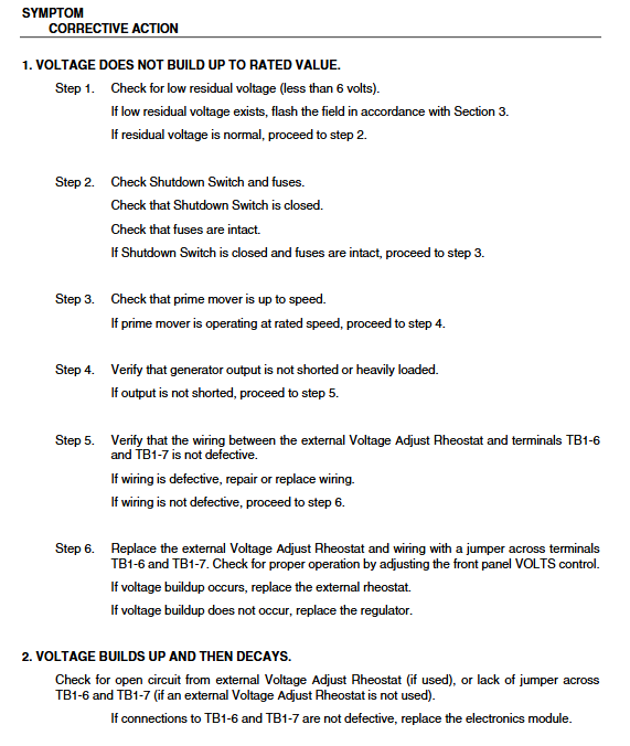
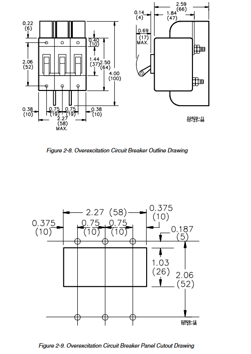
Equipped with an external overexcitation circuit breaker as a secondary backup protection.
6. Requirements for residual voltage during excitation
SSR32/63: Automatic voltage building for generator residual voltage ≥ 6Vac; SSR125 needs to be ≥ 12Vac, and manual magnetization is required if the residual voltage is insufficient.
7. Parallel circuit
Parallel CT secondary rated 5A, capable of supporting 10VA; supports two parallel schemes: reactive power differential (Droop) and cross current differential (cross current).
8. Machinery and Environment
The whole machine is packaged to prevent moisture and dust; Working temperature -40 ℃~+70 ℃, storage temperature -40 ℃~+85 ℃; Strict anti vibration and impact indicators; The overall size is 229 × 282 × 91mm, with a net weight of 5.4kg.
Adjustable panel controls and indicator lights
VOLT (Voltage Regulation): Clockwise boost and counterclockwise buck, with built-in regulation covering ± 10% of each gear, and an external 1k Ω/2W potentiometer for remote ± 10% voltage regulation;
Stab (Stable Damping): Clockwise stable, slow response; The counterclockwise response is fast, and the no-load voltage is prone to oscillation. When debugging, adjust it to no oscillation and the response is balanced;
FREQ (low-frequency inflection point): Raise the low-frequency action point clockwise;
DROOP ADJ: Adjust the amplitude of reactive power drop in parallel for multiple units;
Under FREQ LED: When the frequency is lower than the set value, an alarm will light up.
Optional accessories for system matching
Overexcitation circuit breaker: 20A, 277Vac, dual protection of manual opening and over excitation trip;
SCP250 reactive power/power factor controller;
SBO160 boost module;
CT2~CT50 series parallel current transformers;
EDM200 excitation diode monitor;
EL200 maximum/minimum excitation limiter;
7 BE1/BE3 automatic synchronization device;
8 LDC300 line voltage drop compensator, MVC112 manual excitation unit;
9 high and low voltage isolation transformers (suitable for various generator voltages ranging from 240V to 13.8kV);
10 Surge Suppression Module: Equipped with high impedance power supplies such as PMG and isolation transformers, it absorbs peak voltage from the excitation circuit and protects power devices.
Installation and complete wiring specifications
1. Installation requirements
Suggest vertical installation to ensure heat dissipation; Both the whole machine and surge module can be directly fixed to the generator housing, and can withstand vibration and impact.
2. Definition of key terminals TB1 and TB2
TB2 (power/sampling/excitation)
E1/E2/E3: Three phase voltage sampling; Single/three-phase switching through TB1 jumper;
F+, F -: DC output of excitation winding, strictly distinguish polarity;
3. 4: The AC working power supply of the voltage regulator is directly connected to phases B and C of the generator supply and demand;
1. 2: Parallel CT secondary input.
TB1 (control jumper, external terminal)
21/22 short circuit=single-phase sampling; Disconnect=three-phase sampling;
27/30 jumper=50Hz mode, disconnect=60Hz;
29/30 short circuit=1V/Hz, disconnect=2V/Hz low-frequency curve;
6. 7: External remote voltage regulator potentiometer, short circuit required if not in use;
23, 24: Series connection of external control devices such as reactive power controllers and excitation limiters;
30: Shielding layer grounding terminal.
3. Four standard wiring schemes
Generator busbar direct power supply+three-phase sampling;
Generator busbar direct power supply+single-phase sampling;
3 PMG permanent magnet machine independent power supply (high-frequency power supply, jumper changed to adapt to 120-240Hz);
Multi unit cross differential parallel CT series circuit.
4. Hard wiring taboos
The DC resistance of the excitation winding is lower than the minimum value of the model, and a power resistor must be connected in series;
It is strictly prohibited to disconnect the excitation circuit during operation, which may cause high-voltage breakdown devices; Shutdown is only allowed to cut off the AC power supply of the voltage regulator (3/4 terminal);
When the excitation circuit and generator output are grounded simultaneously, an isolation transformer must be installed;
4 PMG and other high impedance power supplies must be equipped with surge suppression modules.
Single machine startup and debugging process
Complete wiring inspection, verify sampling taps, frequency jumpers, and excitation polarity;
2. Increase the rated speed of the prime mover and observe whether it automatically builds up pressure;
3. No residual voltage excitation operation: The unit is completely shut down, the ≤ 12V DC power supply is connected in series with a 25-30 Ω current limiting resistor, and the F+is connected to the positive and F – is connected to the negative for 3 seconds of magnetization;
Adjust the VOLT knob to the rated voltage;
5 load switching, observe whether the voltage oscillates, and adjust the STAB damping;
6. Low frequency test: Reduce the speed to the turning point, the ENER FREQ light will turn on, and adjust the F knob as needed;
7. Full load verification with voltage regulation accuracy of ≤± 0.25% is considered qualified.
Multi unit parallel operation (two modes)
1. Reactive power adjustment Droop (can be connected to the external network/isolated bus)
Short circuit the CT twice on the switch during single machine operation, and turn off the differential adjustment; Disconnect during parallel operation, automatic voltage drop of inductive load, and natural equal distribution of reactive power; CT is installed in phase B.
2. Cross Current (isolated bus only, prohibited from grid connection)
All CT units are connected in series and closed loop, and there is no drop in bus voltage when connected in parallel; Before grid connection, the series loop needs to be disconnected through the auxiliary contact of the circuit breaker and switched to differential mode.
Parallel standard steps
1. Single machine no-load and load testing are normal, and the adjustment function is verified;
2. Close the circuit after synchronizing the frequency, voltage, phase sequence, and phase of the unit;
After closing, active power is distributed through the speed regulator, and reactive power is evenly distributed by adjusting the DROOP knob;
4. Active power imbalance is caused by a governor fault, while reactive power imbalance is caused by CT polarity/differential wiring errors.
Maintenance, bench testing, and troubleshooting
1. Preventive maintenance
Just need to tighten the terminals regularly, clean the dust on the shell, seal the whole machine without vulnerable small parts, and replace the board/machine directly if there is a fault.
2. Simple bench testing method
External matching AC power supply, excitation end connected in series with ≤ 300W 120V bulb load; Rotate the VOLT knob, and if the bulb brightness changes smoothly and the adjustment is sensitive, it indicates that the voltage regulation circuit is normal; Rotating the TAB will change the speed of light and dark response.
3. Typical Fault Comparison Table
Unable to build voltage: insufficient residual voltage for magnetization, sampling disconnection, low speed, insurance disconnection;
2. Rapid drop after pressure rise: remote voltage regulation circuit open circuit, internal circuit failure;
3. The voltage is too high to be lowered: sampling is missing, sampling tap selection is incorrect;
4. Continuous voltage oscillation: STAB damping is too small, and the no-load excitation voltage is too low;
5. Excessive voltage regulation error: inconsistency between sampling and measuring points, unbalanced three-phase load;
6. Uneven reactive power in parallel: CT polarity reversal, incorrect adjustment settings, and inconsistent sampling types.